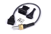
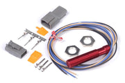
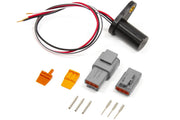
Why the trigger sensor matters so much
The ECU works out engine position and speed from the crank and cam sensors. Every injection pulse and every spark is timed from those signals. A sensor that's the wrong type for the job, mounted with the wrong gap or wired backward can cause anything from a hard start to a misfire at high rpm to timing that wanders under load. Choosing the right type up front saves a lot of fault finding later.
The quick comparison
| Hall effect | Reluctor (variable reluctance) | |
|---|---|---|
| Wires | Usually 3: supply, signal ground, signal | Usually 2: reluctor positive and negative |
| Output | Clean digital square wave, same size at any speed | AC voltage that grows with tooth speed |
| Typical air gap | Roughly 0.040 in (1 mm), check the data sheet | Much tighter, around 0.010 in (0.25 mm) or less |
| Heat tolerance | Limited. Don't count on much above 194 °F (90 °C) unless rated for it | Excellent. Over 392 °F (200 °C) is not unusual |
| ECU setup | Simple | Needs trigger voltage vs rpm set up carefully |
| Mounting | Forgiving | Needs a precise, rigid mount |
How a Hall effect sensor works
A Hall effect sensor has electronics inside. Whenever a magnet or a ferrous tooth passes its tip, it switches its output, giving a crisp on/off square wave. That wave looks the same at cranking speed as it does at redline, which is why Hall sensors are so easy to configure: the ECU sees an identical edge every time a tooth goes by.
The catch is that the sensor has to suit the trigger wheel. Before you buy, check it's compatible with:
- The material of the trigger target.
- Tooth width, the gap between teeth and tooth height.
- Tooth frequency, meaning how many teeth per second it will see at maximum rpm.
We also steer people toward Hall sensors without built-in filtering. Some sensors smooth their output internally, and on a crank wheel with a missing tooth that filtering can hide the very gap the ECU needs to find. Air gap is usually around 0.040 in (1 mm), but the sensor's data sheet has the final word. Heat is the other limit: most Hall sensors aren't happy much past 194 °F (90 °C), so keep them away from exhaust manifolds and turbo housings unless the sensor is rated higher.
If you need a Hall sensor, Haltech offers a single-channel Hall effect sensor, a dual-channel Hall effect sensor for crank and cam from one body, and a GT101-style high frequency Hall sensor for high tooth counts.
How a reluctor sensor works
A reluctor has no electronics at all. It's a permanent magnet, a ferromagnetic pole piece and a coil of wire. As a tooth passes, it disturbs the magnetic field and induces a voltage in the coil. The two ends of that coil are the reluctor positive and negative wires that run to the ECU.
Having nothing electronic inside is exactly why reluctors survive heat so well and why they're so reliable. The trade-offs come from the signal itself:
- Signal size changes with speed. A slow tooth at cranking makes a small voltage; a fast tooth at high rpm makes a big one. Electrical noise rises with speed too.
- The timing edge is harder to pin down. The ECU has to decide exactly where in that changing waveform the tooth actually is, which is why reluctor setups need their trigger voltage levels matched to rpm.
- The air gap is critical. It's far tighter than a Hall sensor's, and it has to be the same at every tooth. A wheel with runout or a flexing bracket changes the signal tooth to tooth.
In practice that means a reluctor needs a rigid, accurately machined mount. The sensor itself is rarely the problem; the bracket usually is.
Wiring either sensor to a Haltech ECU
Hall effect
- Supply: 5V, 8V or 12V, whichever the sensor requires.
- 0V signal ground from the ECU.
- Trigger + to the sensor's signal wire.
Reluctor
- Trigger + to the reluctor's positive side.
- Trigger - to the reluctor's negative side.
Swapping reluctor positive and negative, or mixing Hall and reluctor wiring conventions, gives a signal that sort of works but triggers on the wrong edge. That often shows up as timing that drifts with rpm or intermittent sync loss, which is miserable to chase. Confirm polarity with a scope or trigger log before you start the engine. Our guide to trigger wiring for crank and cam sensors walks through it.
Which should you choose?
If you're adding a sensor to a custom trigger wheel, running moderate temperatures and want the simplest setup, a Hall effect sensor is usually the easy answer. If the sensor has to live somewhere hot, or you're keeping a factory reluctor setup that already works, a reluctor is the tougher option, as long as you give it a precise mount and take the time to set trigger levels properly.
Not sure what your engine already has? Our guide to determining Hall effect sensor pinouts helps identify an unknown sensor, and checking crank and cam angle sensors covers testing. For more on sensor types, see digital Hall effect and optical sensor types and reluctor sensor types.