Why the diode test works
A three-wire Hall sensor has internal junctions between its pins that behave like diodes, conducting one way and blocking the other. The diode test on a multimeter (the setting marked with a triangle and a bar) pushes a small current from the red probe to the black probe and shows a reading only when current can flow. By checking which pairs conduct and in which direction, you can map the pins without powering the sensor. Current flows from the power pin toward both of the others, and from the ground pin toward the signal pin.
Step by step
- Find power. Put the red probe on one wire and touch the black probe to each of the other two in turn. Repeat with the red probe on each wire. The wire that shows a reading to both of the others with the red probe on it is the supply wire.
- Find ground. Of the two wires left, put the red probe on one and the black on the other. If you get a reading, the wire under the red probe is ground. If not, swap probes and check again.
- What's left is signal. The last wire is the sensor output that goes to your ECU input.
Label each wire as you go, and confirm the result with the sensor powered: the signal voltage should switch cleanly between high and low as you pass a piece of steel (or a magnet, depending on the sensor) across the tip. Many need a pullup on the ECU input to show that switching at all.
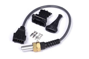
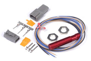
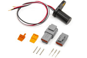
If you'd rather not guess, Haltech's own sensors come documented. The red single channel Hall effect sensor, black dual channel sensor and GT101-style high-frequency sensor are all common choices. For more on sensor types, read Hall effect or reluctor and engine trigger systems explained.