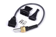
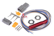
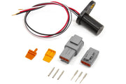
About these distributors
EFI Hardware makes single and dual Hall effect distributors for a range of engines. The dual-sensor versions are the interesting ones for us: one sensor gives eight pulses per cam revolution (one per cylinder on a V8) and the other gives a single pulse. That single sync pulse tells the ECU which cylinder is which, which is exactly what sequential injection and sequential spark need. The design looks to be based on the Holden Commodore VT V8 distributor.
If trigger terms are new to you, read engine trigger systems explained first.
Wiring
A standard Haltech harness brings two shielded 4-core cables to the trigger area: one for Trigger and one for Home. The distributor needs 12 V, a ground and two signals:
| Signal | Distributor wire | Haltech wire (standard) | Haltech wire (after pin swap) |
|---|---|---|---|
| Sensor power, 12 V | Red | Trigger cable, red | Trigger cable, red |
| Sensor ground | Black | Trigger cable, blue | Trigger cable, blue |
| 8-pulse signal to Trigger + | Green | Trigger cable, yellow | Trigger cable, yellow |
| 1-pulse signal to Home + | Blue | Home cable, yellow | Trigger cable, green |
The pin swap: one cable instead of two
Hall sensors don't use the Trigger negative wire (the green one in the Trigger cable, on pin B5), so it's spare. Move that terminal into the Home + position (B2) and all four wires the distributor needs are in a single shielded cable. Here's how:
- On the smaller 26-pin B connector, press the white locking tab in until it clicks. Two small white tabs will rise on the opposite side.
- Pull the yellow wire out of pin 2, insulate the end, and tie it back. It's no longer used.
- Pull the green wire out of pin 5 and push it into pin 2.
- Press both small white tabs back down until they click to lock the terminals.
- Wire the distributor using the last column of the table above.
Give each terminal a gentle tug after it's seated. A terminal that isn't fully locked will cause intermittent sync loss that is miserable to find later.
Setting the TDC offset
The TDC offset tells the ECU how far before cylinder 1's top dead center the reference edge happens. On these distributors it depends on which way the distributor turns.
Clockwise models
The useful edge is the falling edge, 60 degrees before TDC. The catch is that the sync pulse arrives just after cylinder 1's trigger pulse rather than just before it. So the ECU's reference is really the pulse for the cylinder that fires seven cylinders later in the cycle, and we have to add that distance to the angle:
- A four-stroke cycle is 720 crank degrees. Across 8 cylinders, that's 90 degrees each.
- Seven cylinders' worth is 7 x 90 = 630 degrees.
- Add the 60 degree edge angle: 690 degrees TDC offset.
Counter-clockwise models
Here the rising edge is the one to use, at 75 degrees before TDC. The same seven-cylinder shift applies: 630 + 75 = 705 degrees.
Treat either number as a starting point. Always confirm with a timing light: lock the timing in the software, check the mark on the balancer, and adjust the offset until they agree. Our guides on verifying the TDC offset with a dual pickup distributor and setting your TDC offset angle walk through it. If you also drive the coil through the distributor cap, check rotor phasing once the offset is right.
Need the trigger settings screens for these distributors? Ask us and we'll send them over with advice for your build.
Troubleshooting
| Symptom | Usually |
|---|---|
| Trigger count but no sync | Home signal not reaching B2; check the pin swap and the blue distributor wire |
| No trigger signal at all | 12 V or ground missing at the distributor |
| Starts but timing light shows far off | Wrong edge selected for the rotation direction, or offset not yet verified |
| Intermittent sync loss | A terminal not fully locked, or shield/ground issue |
Not sure how your Hall sensor is pinned out? See determining Hall effect sensor pinouts.
FAQ
Can I run sequential injection with a single-sensor version?
Not on its own. Without the one-per-cycle sync signal the ECU can't tell which cylinder is on its power stroke. The dual-sensor version gives it both.
Is the pin swap reversible?
Yes. It's just moving a terminal, so you can put the pins back where they came from.