S3 or S2: what's actually different?
Both ECUs use the same housing, the same two AMP 34-pin connectors (Connector A on keyway 1, Connector C on keyway 2), a built-in 4 bar MAP sensor, an onboard wideband controller, two CAN buses, USB-C and Wi-Fi. The real split is how many cylinders they can drive directly.
| Feature | Nexus S3 | Nexus S2 |
|---|---|---|
| Injector outputs | 8 | 4 |
| Ignition outputs | 8 | 4 |
| Half bridge outputs | 4 | 4 |
| Digital pulsed outputs | 6 | 6 |
| Analog voltage inputs | 11 | 11 |
| Synchronized pulsed inputs | 6 | 6 |
| Knock inputs | 2 | 2 |
| CAN channels | 2 | 2 |
If you're doing a four-cylinder with room to spare, the Nexus S2 covers it. Six and eight cylinders, or a four-cylinder where you want spare injector and ignition channels to use as extra outputs, point you at the Nexus S3. If you need more I/O than either offers, look at the Nexus T2 and T1 or the engine-specific Rebel LS.
In the box, and what you'll probably add
The ECU ships with a USB-C cable, a dust cap for the USB-C port and mounting bolts. The connectors themselves are not included, so plan on one of these:
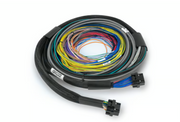
- The S3/S2 universal wire-in harness (8 ft / 2.5 m) for a full custom install.
- Loose AMP 34-pin plug and pin sets (keyway 1 and keyway 2) if you're building your own loom.
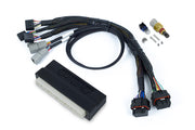
- A plug 'n' play adapter harness where one exists for your car, such as the Honda DC5 adapter.
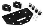
- A tube mount kit if you want the ECU clamped to a roll cage or bar (1.25 in and 1.625 in sizes exist).
- A wideband hardware pack, either Bosch LSU 4.9 or NTK, to use the onboard wideband controller.
On the face of the unit you'll find four status LEDs (Power, DTC, Wi-Fi and Datalog), the USB-C comms port and the two connectors.
Getting online in NSP
The S3 and S2 are programmed with Haltech's NSP software on a Windows laptop. Grab the current installer from the downloads section of Haltech's website, run the setup wizard, then open NSP from the Start menu or desktop icon.
Here's the part we like: plug the USB-C cable into the ECU with nothing else connected and NSP will see it and wake it in a low power mode. In that state the inputs and outputs are switched off, so you can load a base map or run the setup wizard on the bench before the ECU ever goes in the car. It's the safest way to arrive at first start with trigger, injector and ignition settings already sane.
Wi-Fi connection
- Connect over USB-C first and open NSP.
- Find Connections in the navigation tree and turn the Wi-Fi module on.
- Under Connections, open Wi-Fi and choose a network name (SSID) and password. The SSID needs at least one character and the password at least eight.
- Press Apply.
- Turn the ignition on so the ECU is running from main power, then join that network from your laptop's Wi-Fi settings.
The antenna is inside the case, and Wi-Fi only works when the ECU is on its main supply, not USB bench power. Up to two laptops can be on Wi-Fi at once alongside one on USB-C, which is handy when one person drives and another watches. Switch the module off and it's fully powered down. For more, see our Wi-Fi settings article.
Power, ground and the engine control relay
The S3/S2 is meant to be fed through an engine control relay (ECR), not straight from the key. What it needs:
- Pins A18 and A25: +12V from the ECR. Use both.
- Pins A10 and A11: ground, run directly to the battery negative. Use both.
- Pin A13: the ignition switch input from the key.
- ECR output: the ECU grounds this to pull the relay in, so the ECU decides when the whole system is powered.
Pick an ignition feed that stays live in both the Run and Start key positions. Plenty of factory circuits drop out during cranking, and if the ECU browns out while the starter is turning you get hard starts and unnecessary stress on the engine.
Trigger and home inputs
The ECU needs crank and cam information to know engine speed and where each cylinder is in its cycle. A crank sensor alone can't tell compression from exhaust stroke, so it's fine for wasted spark and batch fuel but not for full sequential. On a crank-only engine you'll add a cam sensor if you want sequential. Some engines get everything they need from a single cam-driven sensor.
The trigger inputs handle -10V to +10V, have a selectable 1k2 or 440R pull-up to 5V, can run in full differential mode, survive -75V to +75V indefinitely and read signals up to 48 kHz.
- Hall effect and optical sensors give a 0-5V square wave and usually have power, ground and signal wires. Power them from the +5V or +8V supply, or from a half bridge output set up to supply 12V, depending on the sensor. The internal pull-up normally needs to be on.
- Reluctor (magnetic) sensors are two-wire, self-generating and make an AC sine wave as teeth pass. They need no supply, and the internal pull-up must be off.
Use two-core or four-core shielded cable for trigger and home, and ground the shield at one end only, at battery ground.
Outputs at a glance
| Output type | Key specs | What we use it for |
|---|---|---|
| Injector | Current controlled, 8A peak / 2A hold, 0-55V feedback | Injectors on a common relay-switched +12V feed. Spares make 2A switched or PWM outputs, or slow 0-12V switch inputs |
| Ignition | Global 12V or 5V pull-up, per-channel 270R pull-up, 10 kHz, protected against overtemp, overcurrent and flyback | Coils with built-in ignitors only. Spares become 3A sink outputs or switch inputs |
| Half bridge (HBO) | 8A high or low side, 5A max in push-pull, 18 kHz in DBW mode | Drive-by-wire motors, stepper idle valves, electronic wastegates, or heavy on/off loads |
| Digital pulsed (DPO) | 3A low side, selectable 4k7 pull-up to 12V or 5V, 10 kHz | Relays, idle valves, boost solenoids, oil control valves |
Coils without an internal ignitor draw far more current than an ignition output can supply, and wiring one directly will damage the ECU. Use an external ignitor module for those. Also, keep the ignition system unpowered or disconnected until the firing edge is set correctly in NSP, because the wrong edge can cook both igniter and coils.
For drive-by-wire, any two HBOs can be paired in the DBW wiring settings. They don't need to sit next to each other.
Inputs at a glance
- Analog voltage inputs (11): 0-5V sensors like pressure, temperature and position, sampled 1000 times a second. They can also read on/off switches using the On Voltage and Off Voltage thresholds you set. Turn the 1k pull-up on for two-wire temperature sensors and switches to ground; leave it off for powered sensors like MAP and TPS.
- Synchronized pulsed inputs (6): read frequency, duty, position or state from Hall, optical or reluctor sensors, up to 22.5 kHz. Typical jobs are cam sensors, flex fuel sensors, vehicle speed and flat shift switches.
- Knock inputs (2): for piezo knock sensors on the block. Run shielded twin-core and ground the shield at one end.
Wideband and CAN
The onboard wideband controller runs one Bosch LSU 4.9 or NTK sensor directly, selected in NSP's wideband settings. Need a second sensor, say one per bank? Add a CAN controller like the WB1 or WB2 and run one sensor on each. Our WB1 and WB2 guide covers the details.
CAN 1 and CAN 2 each run up to 1 Mbit/s, each has a switchable 120 ohm terminating resistor, and together they support Haltech's CAN expansion products plus preconfigured vehicle CAN interfaces such as factory clusters.
Common S3/S2 questions
Can I wire an old Elite 550 or 750 loom to an S3?
Don't assume an Elite loom's pin functions line up with the S3. Check our Elite to Nexus S-series pinout swap notes before you plug anything in.
Why won't Wi-Fi connect when I'm on the bench?
Bench power over USB-C doesn't bring the Wi-Fi module up. The ECU has to be on main power with the ignition on.
Does the S2 do sequential injection?
Yes, on up to four cylinders, as long as it has a cam reference. With a crank signal only, you're limited to batch fuel and wasted spark.
Want help choosing between the S2, S3 and a bigger Nexus? Book a free 30-minute consultation.