

Engine management

Sold separately

Sold separately
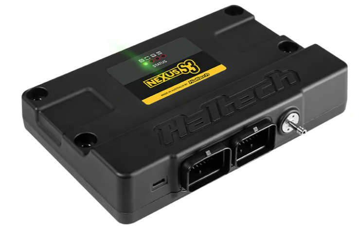
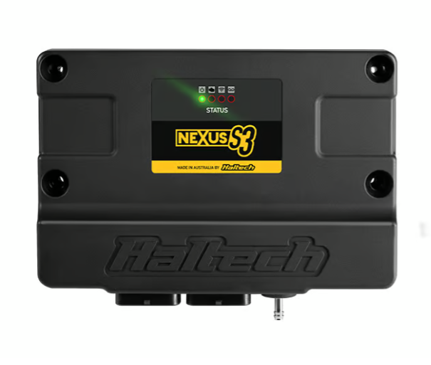
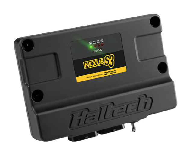
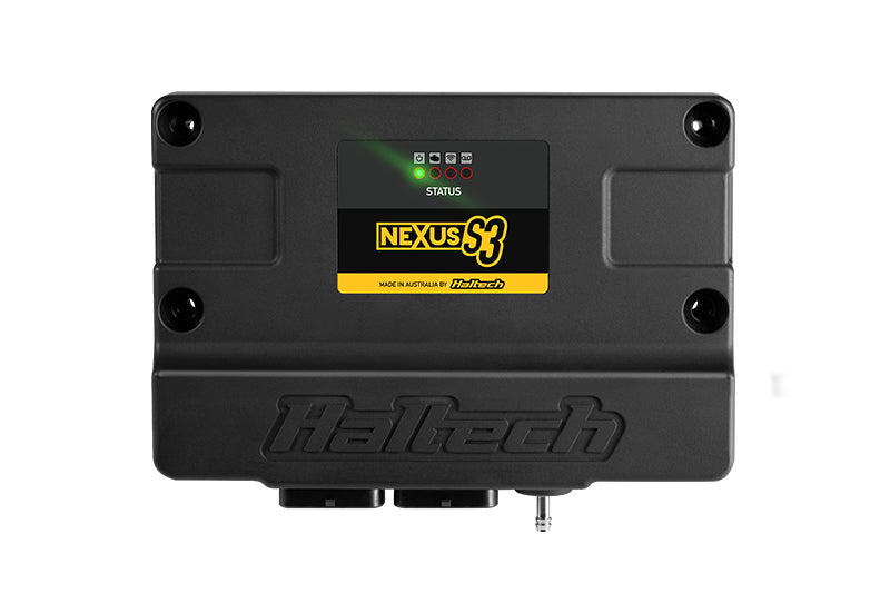
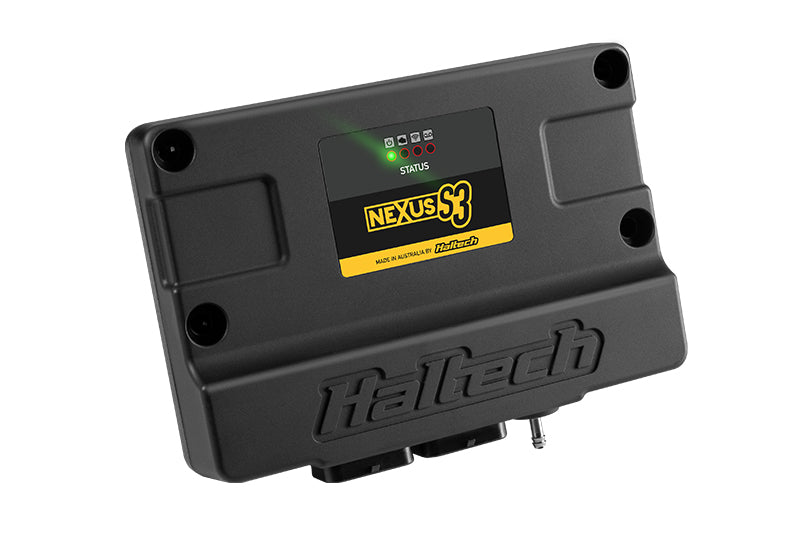
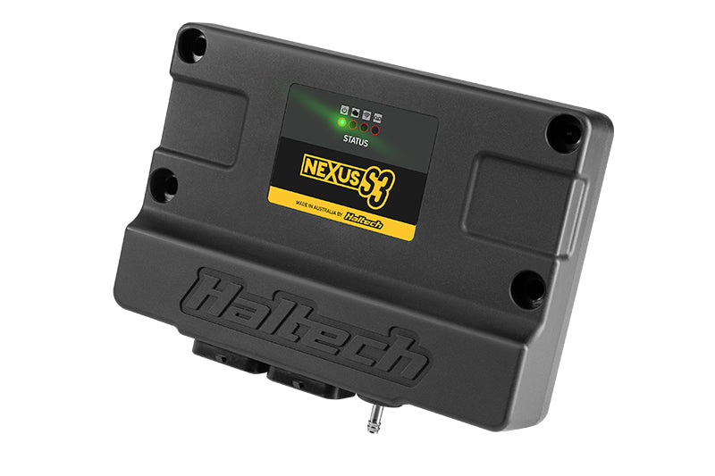
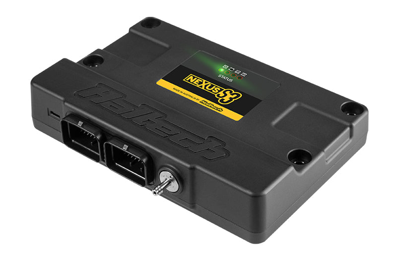
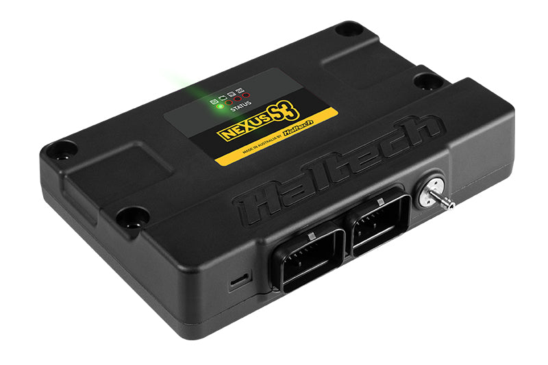
Nexus S3 ECU Only (HT-213000)
SKU: HT-213000
Nexus Must-Haves
Engine management
Sold separately
Sold separately
ECUs always ship FREE with Tuned By Shawn!
Manufacturer Limited Warranty
Nexus S3 ECU Only (HT-213000)
Product details
Description
Small part, real job. Nexus S3 ECU Only and does it the way the rest of a Haltech system expects.
Why It Matters
Correct pinouts the first time, labelled circuits that make diagnosis simple, and factory-grade terminations with no splices to suspect later. Wiring is where builds stall, and purpose-built harnesses are how they don't.
Upgrade your engine's performance and functionality with Haltech's Nexus S3, successor to the Elite 2500. Designed for engines with up to 8 cylinders or 4 rotors, this ECU is perfect for advanced racing applications.
The Details
- SKU: HT-213000
Nexus S3 ECU Pinout
Complete pin-by-pin map of both Nexus S3 ECU connectors. Wire colors are those of the Nexus S3/S2 universal wire-in harness, which is sold separately.
Connector A
34-pin AMP, Keyway 1 - power, ground, injectors, ignition, DPO, HBO and CAN 1.
Looking into the connector on the ECU
| Pin | Function | Harness Wire Color |
|---|---|---|
| A1 | Injector 1 | Blue |
| A2 | Injector 2 | Blue/Black |
| A3 | Injector 3 | Blue/Brown |
| A4 | Injector 4 | Blue/Red |
| A5 | Injector 5 | Blue/Orange |
| A6 | Injector 6 | Blue/Yellow |
| A7 | Injector 7 | Blue/Green |
| A8 | Injector 8 | Blue/Violet |
| A9 | DPO 1 | Violet/Black |
| A10 | Battery Ground Input | Black |
| A11 | Battery Ground Input | Black |
| A12 | DPO 2 | Violet/Brown |
| A13 | Ignition Switch Input | Pink |
| A14 | DPO 3 | Violet/Red |
| A15 | DPO 4 | Violet/Orange |
| A16 | DPO 5 | Violet/Yellow |
| A17 | DPO 6 | Violet/Green |
| A18 | Switched +12V Input | Red |
| A19 | HBO 1 | Brown/Black |
| A20 | HBO 2 | Brown/Red |
| A21 | HBO 3 | Brown/Green |
| A22 | HBO 4 | Brown/Pink |
| A23 | CAN 1 High | White |
| A24 | CAN 1 Low | Blue |
| A25 | Switched +12V Input | Red |
| A26 | ECR Output | Black/Red |
| A27 | Ignition 1 | Yellow/Black |
| A28 | Ignition 2 | Yellow/Red |
| A29 | Ignition 3 | Yellow/Orange |
| A30 | Ignition 4 | Yellow/Green |
| A31 | Ignition 5 | Yellow/Brown |
| A32 | Ignition 6 | Yellow/Blue |
| A33 | Ignition 7 | Yellow/Violet |
| A34 | Ignition 8 | Yellow/Grey |
Connector C
34-pin AMP, Keyway 2 - engine position, sensors, inputs, knock, wideband and CAN 2.
Looking into the connector on the ECU
| Pin | Function | Harness Wire Color |
|---|---|---|
| C1 | Trigger (Crank) + | Yellow |
| C2 | Trigger (Crank) - | Green |
| C3 | Home (Cam) + | Yellow |
| C4 | Home (Cam) - | Green |
| C5 | SPI 1 | Grey/Brown |
| C6 | SPI 2 | Grey/Red |
| C7 | SPI 3 | Grey/Orange |
| C8 | SPI 4 | Grey/Yellow |
| C9 | Sensor +8V Supply | Orange/White |
| C10 | AVI 1 | White |
| C11 | AVI 2 | White/Yellow |
| C12 | AVI 3 | White/Grey |
| C13 | AVI 4 | White/Violet |
| C14 | AVI 5 | White/Green |
| C15 | AVI 6 | White/Orange |
| C16 | AVI 7 | White/Black |
| C17 | AVI 8 | White/Brown |
| C18 | AVI 9 | White/Red |
| C19 | SPI 5 | Grey/Pink |
| C20 | SPI 6 | Grey/Light Green |
| C21 | CAN 2 High | White |
| C22 | CAN 2 Low | Blue |
| C23 | Knock 1 | White |
| C24 | Knock 2 | White |
| C25 | Sensor +5V Supply | Orange |
| C26 | Signal Ground | Black/White |
| C27 | AVI 10 | Light Green |
| C28 | AVI 11 | Light Green/Black |
| C29 | WBI 1 Heater + | Grey |
| C30 | WBI 1 Input | Yellow |
| C31 | WBI 1 Pump | Red |
| C32 | WBI 1 Nernst | Black |
| C33 | WBI 1 Heater - | White |
| C34 | WBI 1 Cal | Green |
Trigger and Home run in shielded four-core cable (Trigger: grey jacket, Home: grey/black jacket). The red +12V and black signal-ground cores in those cables land on Connector A, not Connector C. Knock 1 and Knock 2 each run in shielded two-core cable. Shielded cables should be earthed at one end only.
Pinout data taken from the Haltech Nexus S3 / Nexus S2 Universal Wire-In Harness wiring diagram (HT-182200, revision 1.1) and the Nexus S3/S2 Quick Start Guide. This listing is the ECU only - the wire-in harness, sensors and hardware are sold separately.
Applications
Unsure whether this suits your ECU or build? Send us the details before ordering and we will confirm compatibility.
Tuned By Shawn is a Platinum Haltech Dealer. Questions on compatibility with your ECU or build, send them through before ordering and we will confirm the right part.
If you have any questions, you are always welcome to contact us. We'll get back to you as soon as possible, within 24 hours on weekdays.
-
Shipping Information
Use this text to answer questions in as much detail as possible for your customers.
-
Customer Support
Use this text to answer questions in as much detail as possible for your customers.
-
FAQ’s
Use this text to answer questions in as much detail as possible for your customers.
-
Contact Us
Use this text to answer questions in as much detail as possible for your customers.