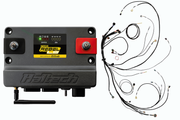
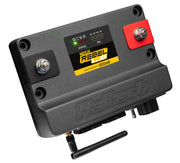
What the Rebel LS is
The Nexus Rebel LS is a Nexus-family ECU built specifically for GM LS engines, both Gen III and Gen IV. Besides running fuel and spark, it has an onboard wideband O2 controller, a built-in data logger and Wi-Fi, so a typical swap doesn't need a separate wideband gauge or logging box. It pairs with a dedicated terminated harness that plugs into the factory sensors and sub-harnesses, and it's tuned with Haltech's NSP software, not ESP.
If you're comparing options, the Rebel JZ is the same idea for Toyota JZ engines, and the Nexus S3 and S2 or T1 and T2 suit builds that need more I/O or a universal setup.
Choosing a kit
Two complete kits are offered. Both use the same ECU (HT-220001), the same main terminated harness (HT-186500), a T56 transmission harness, a Bosch LSU 4.9 wideband with bung, an air temp sensor with bung, and the alternator adapter set. The differences are all about which generation of engine you have.
| HT-220201 (Gen III) | HT-220204 (Gen IV) | |
|---|---|---|
| Throttle | Cable throttle, with a TPS and IAC sub-harness | GM 6-pin drive-by-wire, with the 6-pin DBW adaptor and a Corvette pedal adaptor |
| Injector plugs | EV1 sub-harness | EV6 sub-harness |
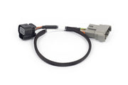
| Sensor adaptors | Gen III valley knock sensor adaptor | Gen IV MAP adaptor and Gen IV oil pressure adaptor |
Mixed-generation engines are common in swaps, so check what's actually on your block rather than going by the model year. Useful extras sold separately include the Multec 2 injector sub-harness, the 8-pin DBW adaptor, the Bosch pedal adaptor with a Bosch pedal, a flex fuel sensor, and a WB2 CAN wideband if you want a second O2 channel.
Planning the install
Decide where the ECU lives before you cut a single battery cable. Under the dash, the glove box, a kick panel or the engine bay all work; the ECU is sealed against dust and splashes, but in the engine bay give it airflow and keep it clear of headers. Then lay the harness out loosely, route it through the firewall grommet, and make sure every branch reaches its sensor without being stretched or leaving a big loop of slack. Only once the routing is right do we start plugging things in, sleeving hot areas, tying everything down, and finally bolting the ECU in place.
Tools you'll want on hand: a laptop for NSP, wire strippers and crimpers, a crimper that can handle 4 AWG battery cable, a multimeter, cable ties, wrenches, a 2 in (51 mm) hole saw if the harness passes into the cabin, and access to welding for the O2 bung.
The harness does not ground the engine. Run a proper strap from the block to the battery. Disconnect the battery while you work, never charge or pull the battery with the engine running, keep fuel and wiring away from heat, and check for fuel leaks and bare wire before first start.
Connection by connection
Power and ignition switch
The ECU gets its own red and black battery leads. Use 4 AWG cable (not supplied) with the included ring terminals and boots, and fuse the positive side; a 100 A fuse is the recommendation. Both leads stay connected at all times. The pink flying lead is the switched 12V wake-up signal. Tap it from the ignition circuit that stays live while cranking, never an accessory circuit, or the ECU will drop out every time you hit the starter. See ignition switch for more.
Coils, injectors and throttle
- Ignition: the harness plugs into the engine's factory coil sub-harnesses, odd and even banks. Bolt the two 13 mm coil ground rings to spare holes at the back of each head. The stock LS coils have built-in igniters. If you change coils, confirm the new ones do too, because a coil without an igniter will damage the ECU.
- Injectors: choose the sub-harness that matches your injector plugs. Every plug is labeled by cylinder. The Rebel LS drives high impedance injectors only.
- Throttle and pedal: the throttle connector takes either the cable-throttle or DBW adaptor. For drive-by-wire, the pedal adaptor also brings in a brake signal that should see 12V when the brake is pressed, which the DBW safety logic relies on.
High-current outputs
| Wire | Job | What we use it for |
|---|---|---|
Red/Blue 12 AWG, AX25+ | User-defined 12V output, up to 25 A | A second pump, fans, a nitrous or transbrake solenoid, a switched feed for accessories, or driving the starter solenoid so the ECU can block cranking unless it's in park/neutral or the clutch/brake is pressed |
| Red/Yellow 12 AWG | Direct fuel pump feed | Lets the ECU prime the pump at key-on and shut it off when it stops seeing engine speed. See fuel pump |
| Red/Orange 12 AWG | Direct thermofan feed | Temperature on/off control, turning on with A/C, and switching off above a road speed if you have a speed sensor. See thermofan |
Sensors
- Cam: LS cam sensor wiring varies by engine, so the harness ships with the signal (yellow) and sensor power (red) wires loose. Pin them to suit your sensor, then fit the wire retainer before plugging in.
- Crank: plugs straight into the sensor behind the starter.
- MAP: the plug fits a Gen III sensor; use the HT-186511 adaptor for a Gen IV sensor. The ECU also has an onboard 4-bar MAP sensor, good to about 43 psi of boost.
- Oil and fuel pressure: both use the early 3-pin style plug. The oil plug fits the factory Gen III sender; later senders need HT-186510. A fuel pressure sensor is optional but we strongly recommend one, so the ECU can compensate for pressure changes and protect the engine if pressure drops.
- Temperatures: coolant plugs into the sensor in the left-hand cylinder head. The kit's air temp sensor comes pre-calibrated in the ECU; mount it in the intake pipe just ahead of the throttle body, especially if the factory MAF and airbox are gone.
- Knock: the plugs suit Gen IV block-side sensors. Valley-mounted Gen III sensors need HT-186508. Once wired, you can set up knock detection.
- Alternator: a DTM-2 plug provides switched 12V, and the kit's adaptors suit 2-pin Bosch, 4-pin Delco and 2-pin Yazaki alternators, using a 470-ohm resistor in place of the dash charge light.
Wideband placement
Have the bung welded in by someone who does it for a living, with the battery disconnected. Put the sensor where it sees all cylinders, usually just past the collector, and ahead of any catalytic converter or air injection, which would skew the reading. Mount it on the top half of the pipe, tilted, so condensation can't collect on the element, and keep the lead off the exhaust. With it in place, the ECU can run closed loop fuel control and lean protection.
Spare I/O, CAN and transmission
In-cabin connectors break out the spare channels: five digital pulsed outputs (switch to ground, 3 A max, good for boost solenoids, shift lights, tachs or relays), two analog voltage inputs (0-5V, with a selectable 1K pull-up for temperature sensors and ground switches), and four synchronized pulsed inputs that can read frequency or duty up to 22.5 kHz as well as voltage, for things like flex fuel or wheel speed. There's a Haltech CAN channel for dashes, keypads, PDMs and expanders (see Haltech CAN), and a transmission connector that the T56 harness uses for vehicle speed. Automatic transmission control was not supported at the time this was written, so ask us about current firmware before planning an auto build.
NSP and the setup wizard
Install NSP from the Haltech downloads area and connect the ECU with the supplied USB-C cable. Here's a feature we love: over USB alone, with no 12V, the ECU wakes up in a low power mode with all inputs and outputs off. That means you can load a base map or build one on the bench, before the ECU ever sees the car.
The wizard walks through seven steps:
- Vehicle name and an optional description, which sets up the folder NSP saves maps and logs to.
- Base engine from the list of LS variants, which fills in displacement and compression.
- Camshaft profile, which adjusts fuel, spark, idle and O2 control defaults.
- Air intake: naturally aspirated or boosted, and cable or DBW throttle. NSP assigns the matching I/O.
- MAP sensor: the onboard 4-bar sensor or an external one picked from the list.
- Fuel system: fuel type, injectors, manifold-referenced or constant pressure regulation, and base pressure, so the ECU can calculate injector pulse width from the start.
- Ignition coil type.
Review the summary, go back and fix anything that's off, and the map is ready to start the engine.
First start checklist
- Oil and coolant filled, belts and hoses checked, no leaks.
- Charged battery, ECU power and engine ground strap in place.
- Every sensor reading plausibly in NSP: crank, cam, MAP, temperatures, throttle.
- Outputs connected: injectors, coils, pump and fan.
- Key on to prime, then confirm fuel pressure and look again for leaks.
- Crank briefly to confirm it turns over cleanly, then start it.
- Watch coolant temperature and wideband and listen for anything odd.
The base map gets it running, but it isn't a tune. Fuel, spark and idle all need to be dialed in for your combination. If you'd rather hand that part to us, book a free 30-minute consultation.
Troubleshooting
| Symptom | Usually |
|---|---|
| ECU drops out while cranking | Pink wire on an accessory circuit instead of the run/start ignition feed |
| No cam signal | Cam plug not pinned to suit that engine's sensor |
| No knock or MAP reading | Gen III and Gen IV sensor styles mixed without the right adaptor |
| Wideband reads lean at idle | Sensor after the cat or near an exhaust leak |
| Nothing responds on the bench | Normal in USB-only low power mode; outputs stay off until the ECU has 12V |
FAQ
Does the Rebel LS work with a Gen III and a Gen IV LS?
Yes. Pick the kit closest to your engine and add adaptors for any mixed-generation parts like knock, MAP or oil pressure sensors.
Do I need a separate wideband controller?
No, one Bosch LSU 4.9 channel is built in and the sensor comes in the kit. Add a CAN wideband only if you want a second bank.
Can it run low impedance injectors?
No, it's high impedance only, which covers the factory LS injectors and most common upgrades.
Want the pinout or connector diagrams for your build? Ask us and we'll send them with advice for your setup.