T1 or T2: which one fits your engine?
Both ECUs run the same NSP software, use the same main connector and have the same sensor inputs, general-purpose outputs and CAN port. The split is fuel and spark channels:
| Nexus T1 | Nexus T2 | |
|---|---|---|
| Built for | 4-cylinder and 2-rotor engines | 6-cylinder and 3-rotor engines |
| Injector drivers | 4 | 6 |
| Ignition outputs | 4 | 6 |
| Everything else | 5 DPOs, 5 AVIs, 2 SPIs, 1 CAN bus, USB-C and Wi-Fi | Same as the T1 |
For a four-cylinder or a 2-rotor like a 13B, the Nexus T1 covers it. For an inline six, a V6 or a 3-rotor 20B, step up to the Nexus T2. Need more I/O than either offers? Compare the Nexus S3 and S2, or add a Nexus IO16 expander over CAN (more on that below).
What you'll want on the parts list
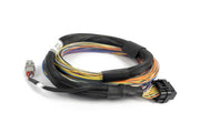
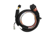
- A harness. Haltech offers a Basic universal wire-in harness (HT-181200) and a Premium universal wire-in harness (HT-181201), both 8 ft (2.5 m) long. If you'd rather build your own loom, the AMP 34-pin plug and pin set (HT-030009) is the connector.
- A wideband. The T1 and T2 read lambda over CAN, so the WB1 single-channel or WB2 dual-channel CAN controller is the natural pairing.
- A relay for ECU power. See the power section below. It isn't optional.
Getting connected in NSP
USB first
Install NSP (Nexus Software Programmer) from the downloads area of Haltech's website, run the setup wizard, then open it from the Start menu or the desktop shortcut. Plug the supplied USB cable into the USB-C port on the ECU. You don't need the car at all for this step: USB alone wakes the ECU in a low-power state where every input and output is switched off. That's the right time to load a basemap or build a new one on the bench, before the ECU ever sees a coil or an injector.
Setting up Wi-Fi
- Go online over USB.
- In the navigation tree, open Connections and turn on the Wireless module.
- Under Connections, pick Wireless, choose an SSID (at least 1 character) and a password (at least 8 characters), then click Apply.
- Turn the ignition on so the ECU is running from main power, then join that network from your laptop's network settings.
A few details that catch people out. The antenna is inside the case, so there's nothing to mount, but Wi-Fi only works on main power, not USB power. Two computers can be on wireless at once, plus a third on USB-C. And when you switch the Wireless module off, it's fully powered down rather than just hidden.
The same Wi-Fi link is what the free Haltech Connect app (iOS and Android) uses. From a phone or tablet you can watch live data, build simple gauges, clear DTCs, assign wiring and change a limited set of parameters. It's handy in the driveway. It isn't a replacement for a laptop when you're tuning.
Power and ground: get this right first
Most "weird" ECU problems we chase on customer cars trace back to power and ground, so here's how we wire every T1 and T2:
- Ground (pin A10) goes straight to the battery negative post. Not a body bolt, not the block.
- Power (pin A26) is fused and fed through an engine control relay (ECR).
- The relay coil is triggered by a switched 12V from the ignition switch that stays live in both RUN and START. Many ignition switches drop some circuits while cranking. If your ECR is on one of those, the ECU browns out mid-crank, and that makes for hard starts and needless wear.
Haltech's diagram shows their HT-030205 micro relay. If you use that Haltech micro relay, the diagram applies as drawn. With any other relay, wire it to that relay's own pin schematic, since pin numbering isn't universal. The ECU also provides a +5V sensor supply on A9.
Need this diagram? Ask us and we'll send it over with advice for your build.
Inputs, one type at a time
Crank (trigger) and cam (home)
Engine speed and position come from these two inputs. Most engines use one crank and one cam sensor. Some get everything they need from a cam sensor alone. A crank sensor alone can't tell the compression stroke from the exhaust stroke, so if you want sequential injection or coil-on-plug without wasted spark, you'll need to add a cam sensor.
- Hall effect or optical sensors give a 0-5V square wave and usually have three wires: supply, ground and signal. Power them from the ECU's 12V (A26) or 5V (A9) as the sensor requires, and turn the internal pull-up on in NSP.
- Reluctor (VR) sensors make their own AC signal from the passing teeth and have two wires, signal + and signal −. They need no power, and the internal pull-up must be off.
Run shielded cable (two-core or four-core) and ground the shield at the battery end only. Grounding both ends creates a loop that picks up the very noise the shield is there to block. Electrically, the trigger inputs accept ±10V signals, survive ±75V indefinitely, handle up to 48 kHz and have a selectable 1k2 or 440R pull-up with a selectable ground reference.
Analog voltage inputs (AVI): 5 channels
These read 0-5V sensors: pressure, temperature and position. They sample 1,000 times a second and tolerate −10V to +30V. They also work as switch inputs: you set an On Voltage and Off Voltage in NSP, which suits things like an A/C request or a launch control enable switch.
Each AVI has a 1k pull-up to 5V you can toggle in software. Our rule of thumb: pull-up on for two-wire temperature sensors and switches that ground the input; pull-up off for anything with its own 5V supply, like a MAP sensor or TPS.
Synchronized pulsed inputs (SPI): 2 channels
SPIs measure frequency, duty, position or state, which makes them the place for VVT cam sensors, flex fuel sensors and vehicle speed sensors. They work with both Hall/optical and reluctor sensors, read up to 22.5 kHz and survive −15V to +30V. Note that SPI 2 doubles as the knock input, so plan ahead if you want both.
Knock input
A piezo knock sensor bolted to the block lets the ECU hear detonation and pull timing. Use twin-core shielded cable, shield grounded at the battery end only. Our knock wiring notes and the genuine Bosch knock sensor are good starting points.
Outputs
| Output | Count (T1 / T2) | Key specs | Spare channels can be |
|---|---|---|---|
| Injector drivers | 4 / 6 | Current controlled, 8A peak and 2A hold, 0-55V feedback | 2A switched or PWM outputs, or low-speed 0-12V switch inputs |
| Ignition outputs | 4 / 6 | 10 kHz, global 12V or 5V pull-up, per-channel 270R pull-up, overtemp, overcurrent and flyback protected, 0-27V feedback | 3A sinking DPOs or PWM, or low-speed switch inputs |
| Digital pulsed outputs (DPO) | 5 / 5 | 3A low-side drive, selectable 4k7 pull-up to 12V or 5V, 10 kHz, overcurrent, flyback and overtemp protected, 0-27V feedback | Low-speed switch inputs |
Injectors
Wire each injector's ground side to its matching cylinder output, and feed all of them from one relay-switched +12V. The ECU fires an injector by grounding that pin for the commanded pulse width.
Ignition
The ignition outputs switch between 12V and ground to tell a coil when to charge and when to fire. Drive coils directly only if they have a built-in igniter (like the LS1-style smart coil). A "dumb" coil with no igniter pulls far more current than the output can handle, and connecting one directly will damage the ECU. Those need an external igniter module. If you're not sure which you have, our article on internal igniter or not explains how to tell.
An ignition module or coil can be damaged if the ECU drives it with the wrong firing edge. Unplug the ignition or cut its power until you've set the ignition settings in NSP and double-checked them. Then reconnect.
DPOs
DPOs ground-switch a load, or pulse it at a set frequency and duty. At 3A they can run boost solenoids, VVT oil control valves and idle valves directly. For big loads like fuel pumps and thermofans, let the DPO switch a relay and let the relay carry the current.
CAN: one bus, lots of devices
The T1 and T2 have a single CAN channel on the main connector. Through a Haltech CAN hub it can run wideband controllers, a dash display, CAN keypads and the Nexus IO16 expander, which is the easy way around the T-series' I/O limits. The Haltech CAN system article covers the settings side.
Pinout and dimensions
Haltech publishes a full pinout, dimension drawing, LED status chart and spec sheet for the T1 and T2. Keep the pinout open when you pin a connector or assign I/O in NSP, and check the dimensions before you commit to a mounting spot.
Need this diagram? Ask us and we'll send it over with advice for your build.
Nexus T1 and T2 FAQ
Can I tune a Nexus T1 or T2 without a laptop?
You can monitor it, clear codes and change basic settings from the Haltech Connect app. Full tuning still happens in NSP on a Windows laptop, over USB or Wi-Fi.
Why won't my ECU show up on Wi-Fi?
Check that the Wireless module is enabled under Connections and that the ignition is on. Wi-Fi doesn't run on USB power alone, and it's completely off when the module is disabled.
Can the T2 run a V8?
It's rated for six cylinders and three rotors. For a V8 or more complex builds, look at the larger Nexus ECUs, or book a free consultation and we'll help you choose.