Which alternator do you have?
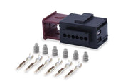
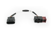
The VE Commodore alternator looks a lot like the units on earlier LS-powered Commodores, but inside it has a regulator that takes a PWM command instead of setting voltage on its own. The easiest way to tell them apart is the plug: the earlier alternator uses a larger connector, while the PWM version has a smaller one. GM made the change around 2006.
How the control signal works
| Item | Detail |
|---|---|
| Control pin | Pin 1, the "Turn On Signal" |
| Signal type | +5V PWM from the ECU |
| Frequency | 128 Hz |
| Normal duty range | 5 to 95% |
| With no signal | Self-excites and defaults to 13.8V |
| Field Duty Cycle Signal pin | Feedback for the factory ECU and BCM; not needed by the Haltech |
The ECU varies the duty cycle to ask for a particular charging voltage. Because the alternator falls back to 13.8V when it isn't being commanded, a broken control wire won't flatten the battery or cook it. You'll just lose the ability to adjust the setpoint.
The Field Duty Cycle Signal pin reports what the alternator is doing back to the factory ECU and body control module. If the car still uses a factory BCM that expects it, leave that wire in place for the BCM, but it doesn't need to go to the Haltech.
Setting it up in NSP
In NSP, you'll assign the alternator control function to a spare output capable of driving a 5V PWM signal at 128 Hz, then set the target voltage and base duty. Our alternator control wiring page covers the output side.
When you first start the car, log battery voltage and alternator duty together. Voltage should settle near your target, and changing the target should move it. If voltage sits at about 13.8V no matter what you ask for, the alternator isn't seeing the signal: check the pin 1 wiring, the output assignment and the frequency.
The alternator pinout and the NSP settings screens are shown in diagrams we don't reproduce here. Need this diagram? Ask us and we'll send it over with advice for your build.
FAQ
Can I just leave it unconnected?
Yes. It will charge at its 13.8V default. ECU control is worth adding when you want to pick the charging voltage yourself, for example a little higher on a car with a big audio system or several electric pumps.
Does this work on the earlier alternator?
No. The older, large-connector alternator regulates itself differently, so this PWM setup doesn't apply. Not sure which you have? Book a free consultation and we'll help you work it out.