Why every build should log oil pressure
A dash gauge only helps if the driver is looking at it at the right moment, and on a track or a drag strip they won't be. An oil pressure sensor wired to the ECU gives you two things a gauge can't: a permanent record in every log, and the ability for the ECU to protect the engine on its own when pressure falls away. Oil surge in a long corner, a failing pump or a spun bearing all show up in the data, often before anything sounds wrong.
Sensor and wiring
Oil pressure sensors are powered sensors, normally with three wires:
- 5V supply from the ECU
- Signal back to the ECU
- Signal ground
The signal goes to an analog voltage input (AVI), and any free AVI will do. Assign it in the Oil Pressure Wiring node. Because the sensor supplies its own output, we leave the pull up disabled; a pull up would skew the reading.
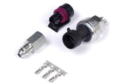
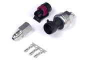
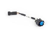
This function is for the sensor reading pressure inside the engine's oiling system. Pick a sensor with sensible range for your engine. The 150 psi TI sensor suits most engines, and the 250 psi version is there for high-pressure race oiling systems. On a Nexus Rebel LS with a Gen IV engine, the Gen IV oil pressure sensor adaptor harness saves splicing.
Calibration
The main Oil Pressure node holds the calibration table that turns sensor voltage into pressure. If the sensor came from Haltech, click Load from File and pick the matching calibration. For anything else, enter the voltage and pressure points from the sensor's data sheet. Save to File lets you keep your own calibration for the next car.
Always sanity-check the result. With the engine off, the reading should sit at or very near zero. With the engine idling warm, compare it against a mechanical gauge if you have any doubt.
The oil pressure safety system
This is the part that saves engines. It has two pieces that work together: a table saying what pressure is acceptable, and a set of conditions saying when the ECU should check.
Oil Pressure Minimum table
This table sets the lowest pressure the ECU will accept. It's usually mapped against engine RPM, because oil pressure naturally rises with pump speed; what's normal at idle would be alarming at 6,000 RPM. You can make it 3D by adding a second axis such as oil temperature, since hot, thin oil makes less pressure than cold oil. That lets you avoid false alarms on a cold start while still catching a real problem once the oil is hot. The table only becomes active once the oil pressure safety diagnostics are switched on.
Operating conditions
| Setting | What it does | Our advice |
|---|---|---|
| Minimum RPM | The engine must be above this speed for the check to run | Above cranking and idle speed, so starting and shutting down don't trip it |
| Precondition | Use MAP, TPS or both as a load condition | Pick the one that best tells you the engine is working hard |
| Minimum MAP / Minimum TPS | The load threshold for the chosen precondition | Set so the check covers real driving, not coasting |
| DTC Delay | How long all conditions and low pressure must last before the code sets | Short enough to protect the engine, long enough to ignore a momentary blip |
| DTC Severity | How hard the ECU reacts when it triggers | Tie it to an engine protection action that actually reduces load |
Put together, the logic reads like this: if RPM is above the minimum, load meets the precondition, and pressure stays below the Oil Pressure Minimum table for longer than the delay, raise the DTC at the chosen severity.
Worked example
Say you log a healthy engine and see pressure climb steadily with RPM once it's warm. A sensible minimum table sits comfortably below that logged curve at every RPM, with extra margin at the hot-oil end if you've added an oil temperature axis. If the car later surges oil in a long sweeper and pressure dips under that line for longer than the delay, the ECU sets the code and engine protection pulls power before the bearings pay for it. The exact numbers depend on your engine builder's specs and your own logs, so start conservative and refine.
Sensor fault diagnostics
Separately from low pressure, the Diagnostics node can flag a faulty sensor using high and low voltage DTCs, each with its own severity that maps to an engine protection level. A reading pinned near 0 V or the full 5 V almost always means an open circuit or short, not real pressure. Enable these so a broken wire doesn't masquerade as either perfect or zero oil pressure.
The Display node simply sets the minimum and maximum for gauges and numeric readouts. Match it to your sensor's range so the gauge is readable.
Troubleshooting
| Symptom | Usually |
|---|---|
| Reads pressure with engine off | Wrong calibration, or pull up enabled |
| Reads zero or maximum all the time | Wiring fault, missing 5V supply or wrong AVI assigned |
| Safety system trips on cold start or at idle | Minimum RPM too low, or minimum table too high at low RPM |
| Safety system trips when hot | Add an oil temperature axis, or investigate a real pressure problem |
| Never triggers in testing | Diagnostics not enabled, or preconditions never met |
Oil pressure FAQ
Can I use my factory oil pressure switch instead?
A switch only tells you pressure is above or below one point. A proper sensor lets the ECU compare pressure to a target at every RPM, which is far better protection.
Should the minimum table be mapped against oil temperature?
If you log oil temperature, yes. It makes the protection accurate across cold starts and hot laps.
What should my minimum oil pressure be?
That depends on the engine, so use your engine builder's figures and your own logs. For more on building a protection strategy, read our oil pressure and engine protection guide, or book a free consultation.