How the Gen IV trigger works
The crankshaft carries a reluctor wheel with a 60-2 pattern: sixty evenly spaced tooth positions with two teeth missing. You'll often hear it called 58x, because 58 teeth are actually there. The missing-tooth gap is how the ECU finds its place, but the timing reference isn't the gap itself. The ECU times the engine from the first real tooth that follows the gap.
The camshaft uses a 4x pattern made up of two small teeth and two large teeth, read by a sensor in the front timing cover.
GM moved to this layout from the Gen III 24x system for good reasons:
- No edge-swapping problems with big cams. The 24x setup could misbehave with aggressive camshafts. The 58x wheel avoids that issue.
- Crank-only running. The engine can half-sync and keep running from the crank sensor alone, which adds a layer of redundancy if the cam signal is lost.
Crank sensor
It sits above the starter, toward the back of the block. Despite what a lot of people call it, the Gen IV crank sensor is a Hall effect sensor, not a reluctor. Here's how it connects:
| Haltech wire color | Job | Goes to crank sensor pin |
|---|---|---|
| Red | 12V+ supply | C |
| Yellow | Trigger + signal | A |
| Blue | Signal ground | B |
Gen IV crank sensors are gray. Gen III sensors are black, are a reluctor design with built-in conversion to a Hall-style output, and will not work with the Gen IV 58x crank wheel. If you're building a hybrid engine from mixed parts, check the color before anything else.
Cam sensor
The Gen IV cam sensor is also a standard Hall effect type, mounted in the front timing cover. Some engines use a short extension lead between the sensor and the main harness, so don't be surprised if the connector isn't where you expect it. If you're building your own loom, confirm the cam sensor pinout against the terminated harness quick start guide or the factory workshop manual for your vehicle before you pin anything.
Setting it up in the ECU
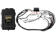
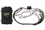
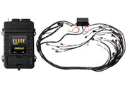
If you're using a Haltech terminated harness, like the Elite 2500 Gen IV LSx DBW-ready harness kit or its non-DBW version, the trigger wiring is already done for you. On a Nexus Rebel LS, it's plug and play.
Either way, before the first start:
- Load a base map or trigger setup that matches the Gen IV 58x crank and 4x cam.
- Crank the engine and confirm the ECU shows a steady RPM and trigger sync.
- Check base timing with a timing light and adjust the trigger offset until the ECU and the engine agree.
Need the trigger configuration screenshots or the OEM wiring references for your application? Ask us and we'll send them over with advice for your build.
For more on these engines, see LS2-LS3 Gen IV engine information, compare the older LS1 trigger, or read engine trigger systems explained.