LS1 at a glance
| Spec | LS1 (Gen III) |
|---|---|
| Layout | V8, cylinders 1-3-5-7 on the right-hand bank |
| Displacement | 346 ci (5665cc) |
| Firing order | 1-8-7-2-6-5-4-3 |
| Injection | Sequential port injection, high-impedance injectors, returnless fuel at fixed pressure |
| Factory injectors | 230cc on early engines, 250cc on later ones |
| Ignition | Coil per cylinder with built-in igniters |
| Trigger | 24x crank wheel, single half-moon cam target |
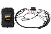
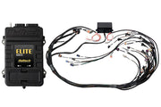
If you want the least wiring, Haltech makes Elite 2500 kits for the Gen III, including the Elite 2500 GM Gen III LS1 and LS6 kit, the non-DBW version for cable throttle engines, and the earlier Elite 2000/2500 Gen III kit.
Crank and cam triggers
The crank carries a 24-tooth reluctor wheel and the cam gear has a half-moon target, which reads high for roughly half of each cam revolution and low for the other half. For the software side, see our LS1 trigger setup article.
Crank sensor
This one surprises people. It's a magnetic sensor, but it has conditioning electronics inside, so what comes out of the plug is a clean digital square wave. Set the crank input up as Hall Effect, not reluctor. Use the falling edge: those edges are evenly spaced. The rising edges carry the pattern's unique timing and the Elite can't use them. You'll find the sensor on the block above the starter, toward the rear.
Color matters. Gen III crank sensors are black. Gen IV sensors are grey and will not read a Gen III wheel, even though they look like they should fit.
Cam sensor
A normal three-wire Hall sensor, found at the back of the engine on top of the valley on Gen III blocks.
Both sensors share the same pin layout, so one table covers them:
| Haltech wire | Crank sensor pin | Cam sensor pin |
|---|---|---|
| Trigger/Home signal (yellow) | A | A |
| Signal ground (blue) | B | B |
| 12V supply (red) | C | C |
Ignition coils
Each cylinder has its own coil on the rocker cover, with the igniter built in, so they wire straight to the ECU's ignition outputs in direct fire. Ground both pin A and pin B to the cylinder head. In the software choose Constant Charge dwell with a Falling ignition edge.
Set to a rising edge, these coils will be damaged. Double-check the edge before you ever crank the engine. Replacement LS1 coils and coil plugs are available if you're building a fresh harness.
Throttle: drive-by-wire or cable
Drive-by-wire models
DBW engines use a single electronic throttle body, and only the Elite 1500 or Elite 2500 can drive it. One catch: on the VZ Commodore, the throttle and pedal don't connect to the engine ECU at all. They go to a separate TAC module. With a Haltech you wire them directly to the ECU instead.
| Haltech connection | Throttle body pin | Job |
|---|---|---|
| DBW 1 (brown/black) | A | Motor drive |
| DBW 2 (brown/red) | C | Motor drive |
| Signal ground (black/white) | B and D | Sensor grounds |
| 5V+ (orange) | E and H | Sensor supply |
| AVI-2 (orange/black) | G | Position sensor 1 |
| AVI-3 (orange/red) | F | Position sensor 2 |
The VZ pedal also needs wiring to the ECU's pedal inputs. For the full DBW picture, including calibration, read drive-by-wire on the Elite.
Cable throttle models
The throttle position sensor is a standard three-wire: pin A is 5V+, pin B is signal ground and pin C is the signal to an analog input.
Idle control
DBW engines idle on the throttle blade. Cable-throttle engines use a four-wire stepper motor idle valve, which needs an Elite 1000 or higher. The Elite 550, 750 and 950 can't run it.
- Stepper wiring: valve pins A, B, C and D go to Stepper 4, 3, 2 and 1 respectively.
- Settings: Drive Type
Both, 240 steps, speed 75.
More on this in stepper outputs.
Sensors and calibrations
| Sensor | Where and how | Calibration |
|---|---|---|
| MAP | On the intake manifold. Pin A ground, B signal, C 5V+ | MAP - GM 1 Bar.cal |
| Coolant temp | Left head, near the cylinder 2 exhaust. Two wires, either way round | Temperature - Holden VP V8 Coolant Sensor.cal |
| Air temp | In the airbox. Two wires, either way round | Temperature - Holden VP V8 Air Sensor.cal |
| Oil pressure | 130 psi sensor. A ground, B 5V+, C signal to a spare AVI | 0.5V = 0 psi, 4.5V = 130 psi |
The temperature calibrations assume the ECU's 1k pull-up to 5V is on. The factory Delphi connectors on the temp sensors are the kind where you thread the wire through the housing first, crimp the terminal, then pull it back to lock. Since the factory MAP sensor is a 1-bar unit, a boosted build will need a higher range sensor, like a 3-bar GM MAP sensor.
O2, knock and MAF
O2 sensors
The factory front sensors are four-wire narrowbands. Replace them with a wideband kit such as the WB2, which covers both banks. If you do keep a narrowband, remember its black wire is the signal, not ground, and it goes to AVI 1 or AVI 6. Grey is signal ground and the two white wires are the heater (12V switched and chassis ground, not signal ground). If you want the ECU to switch the heater ground, use an injector, stepper or DPO output. Never an ignition output.
Knock sensors
The two factory sensors sit in the valley and are an older resonant design. They work, but they fail often and they're mounted to hear front to back rather than bank to bank. We prefer modern flat "donut" sensors like the Bosch knock sensor, mounted on the outside of each bank for better per-bank control.
MAF
Most Haltech installs delete it, but it can be used. The 3-wire version has yellow signal (to a spare AVI), black/white ground and pink 12V switched. The 5-wire version adds an air temp sensor: tan signal (AVI 7 is typical) and purple ground, with the MAF on yellow signal, black/white ground and pink 12V.
4L80E transmission
If the engine is backed by a 4L80E, the ECU has to handle shifting and torque converter lock-up, so plan your outputs for it.
Troubleshooting
| Symptom | Usually |
|---|---|
| No crank signal at all | A grey Gen IV sensor on a Gen III wheel, or the input set to reluctor instead of Hall |
| Position errors after a cam swap | The cam edge now sits too close to a crank edge (see below) |
| Coils getting hot or failing | Rising edge selected instead of falling |
| Temps read wildly wrong | Pull-up not enabled on that input |
Trigger errors after a cam swap
A new cam can move the cam signal's edge close to one of the crank edges. If it hops from one side of that crank edge to the other, the ECU loses engine position. Watch the Home Percentage of Valid Travel channel. Values near 0% or 100% mean the edges are too close. Two fixes:
- Switch to the other cam edge and move the TDC offset by 360 degrees, adding or subtracting so the result stays between 0 and 720.
- Add Home filtering of 2 or 3, which delays the falling edge enough to clear the crank edge. Expect the Home % reading to climb with RPM.
Mixing Gen III and Gen IV trigger parts
| Crank wheel | Cam target | Works? | Trigger type to select |
|---|---|---|---|
| Gen III 24x | Gen III 1x | Yes | General Motors - LSx Gen III (24x + 1x) |
| Gen III 24x | Gen IV 4x | No | Not supported |
| Gen IV 58x (60-2) | Gen III 1x | Yes | Generic missing tooth, single tooth home, on crank, 60 teeth, 2 missing |
| Gen IV 58x (60-2) | Gen IV 4x | Yes | General Motors - LSx Gen IV (58x + 4x) |
Building from scratch? We'd pick the Gen IV trigger. It tolerates more cam movement before errors show up, and the missing-tooth wheel syncs faster, starts quicker and gives more redundancy. Our LS2/LS3 Gen IV engine guide covers that side.
FAQ
Can I use a Gen IV crank sensor on an LS1?
Not on a Gen III 24x wheel. The sensor and wheel must match, or you'll see no crank signal.
Which Elite do I need for a DBW LS1?
An Elite 1500 or 2500. Those are the Elite models that can control the LS1's electronic throttle.
Need the factory ECU pinout or sensor diagrams?
Ask us and we'll send them over with advice for your build.