Know your generation first
Suzuki's GSX1300R comes in two broad generations, and almost every wiring decision depends on which one you have. Both are inline fours with a 1-2-4-3 firing order and cylinder 1 on the left as seen from the rider's seat.
| Gen 1 (1999-2007) | Gen 2 (2008 on) | |
|---|---|---|
| Displacement | 1299cc | 1340cc |
| Injectors | 4, rated 330cc/min | 8 (4 primary, 4 staged secondary), all rated 280cc/min |
| Crank trigger | Reluctor. 8 teeth on 1999-2001, 24-1 on 2002-2007 | Reluctor, 24-2 |
| Cam sensor | Reluctor | Hall effect, 5V powered |
| Factory ECU | 16-bit on 8-tooth bikes, 32-bit on 24-1 bikes | Check the pinout diagram for your bike |
Triggers
On every version the crank trigger reads a wheel on the flywheel/stator. Because both generations use a reluctor (magnetic) crank sensor, polarity matters: if the ECU sees the signal inverted, it will struggle to find the missing teeth. Haltech's crank wiring for the reluctor sensor is:
- OEM green wire (OEM ECU pin 14) to Haltech Trigger + (yellow)
- OEM blue wire (OEM ECU pin 31) to Haltech Trigger - (green)
The Gen 2 Hall effect cam sensor connects as: red to 5V+, black/yellow to Home +, black/brown to signal ground. The Gen 1 cam sensor is a reluctor and wires like any two-wire magnetic sensor.
Trigger configuration differs for the 8-tooth, 24-1 and 24-2 versions. Confirm the tooth count on your bike before loading any settings, then verify on the trigger scope. Our guide to trigger wiring covers shielding and polarity.
Injectors
A Gen 1 is simple: four injectors, one per cylinder. A Gen 2 adds a second bank of four that stage in at higher load. If you keep all eight, the ECU needs enough injector outputs and a staging strategy. Many conversions run only the primaries and upsize them, which keeps the setup simpler.
Ignition
Suzuki hid the igniters inside the factory ECU, so the stock 2-pin Denso coils are "dumb" coils that need an external igniter. A four-channel unit such as the Haltech HPI4 is the usual answer. Start with a dwell of 1.5 ms at 14V, the figure listed for these coils.
Wiring 2-pin coils straight to an ECU ignition output without an igniter will damage the output. Always put an igniter between them.
Sensors
| Sensor | OEM wire colors to Haltech | Notes |
|---|---|---|
| TPS | Red 5V+, purple/black signal, black/brown signal ground | Calibrate closed and wide open once wired |
| MAP (Suzuki's "IAPS") | Haltech's reference lists red as signal ground, green/black as signal and black/brown as 5V+ | This reverses the TPS colors, so meter the harness before powering it |
| Coolant temp | Two wires, not polarity sensitive | Use the Hayabusa calibration built for a 1k pullup to 5V |
| Air temp | Two wires, not polarity sensitive | Same 1k pullup style calibration |
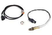
| O2 | Factory sensor is narrowband | Fit a wideband for tuning |
| Gear position | Analog signal | Wire to a spare AVI for gear-based strategies |
The speed sensor is Hall effect, but on both generations it feeds the dash, and the dash sends speed to the factory ECU over a serial link. To get speed into a Haltech, share the sensor's signal wire with a spare SPI while leaving the dash connected.
Idle valve and sub-throttle
Idle air is controlled by a four-wire stepper motor, which any two-connector Elite can drive:
| OEM wire | Function | Haltech |
|---|---|---|
| White/black | 1A | Stepper 1 |
| Black/light green | 1B | Stepper 2 |
| Purple/white | 2A | Stepper 3 |
| Green | 2B | Stepper 4 |
Like most sport bikes, both generations also have a secondary set of throttle plates between the airbox and the cable-operated throttles. A stepper motor moves them and a position sensor (red 5V+, yellow/white signal, black/brown ground) reports where they are, much like a small drive by wire system. Suzuki used it to trim power regardless of what the rider asked for. The sub-throttle stepper uses the same color-to-stepper mapping as the idle valve above. See stepper outputs and idle control for setup.
ECU connectors and base maps
Handy detail: the Gen 1 factory ECU uses the same connector family as the two-connector Elite range. Don't assume the same for a Gen 2; check its connectors against the pinout first. Factory pinout diagrams exist for both. Need one? Ask us and we'll send it over with advice for your build.
A dedicated Hayabusa base map and install pack are not published yet. We build these tunes regularly, so if you're starting a Busa project, book a free consultation and we'll help you choose parts and a starting map.
FAQ
Which Hayabusa is easier to convert?
Gen 1, usually. Four injectors, familiar connectors and no staged injection keep it simple. Gen 2 adds more hardware, including staged injectors and a 5V-powered Hall effect cam sensor.
Can I keep the factory coils?
Yes, with an external igniter like the HPI4. Other Suzuki engine notes are in our G13B and M16A articles.