EZ30D at a glance
Of the Elite range, the Elite 2500 is the Elite model this engine is supported on, and it can read both of the factory knock sensors.
| Spec | EZ30D |
|---|---|
| Layout | Horizontally opposed 6 cylinder |
| Displacement | 2997cc (about 183 cubic inches) |
| Firing order | 1-6-3-2-5-4 |
| Cylinder numbering | Viewed from the front of the engine, 1, 3 and 5 are on the left bank; 2, 4 and 6 are on the right |
| Found in | Third and fourth generation Liberty/Legacy, and the Outback |
| OEM injector flow | 260 cc/min |
If you want a plug-in route rather than a wire-in, the Elite 2500 + Liberty/Legacy Gen 4 3.0R and GT Plug 'n' Play kit connects the ECU to the factory loom.
Know which EZ30D you have
Subaru made two quite different versions, and the differences decide how you wire throttle, idle and cams.
| Feature | Series 1 (MY00-03) | Series 2 (MY04 on) |
|---|---|---|
| Throttle | Cable, with a separate TPS | Drive by wire |
| Idle control | 3-pin idle air valve on the throttle body | Handled by the DBW throttle |
| Cam timing | AVCS on the intake cams | AVCS on the intake cams |
| Cam lift | None | AVLS switching lift on the intake cams |
| Intake manifold | Aluminum, with variable length resonance chamber | Plastic |
| Exhaust ports | Siamesed, one port per head | Individual ports |
| Other | 10.7:1 compression | Lighter block, hollow cams |
Crank and cam triggers
The trigger pattern is Subaru specific, so it's worth understanding before you look at a trigger scope. The crank wheel sits where the flywheel bolts on and is based on 36 teeth. It has one gap of two missing teeth, and roughly a third of a turn away there's a second feature made of two 2-tooth gaps with a single tooth between them. The cam signal comes from three evenly spaced teeth on one camshaft on bank 2.
The crank sensor is a reluctor type mounted at the rear of the block. The cam sensors are Hall effect units at the back of the cylinder heads.
| Sensor pin | Haltech wire | Function |
|---|---|---|
| Crank 1 | Trigger 4-core, yellow | Reluctor positive |
| Crank 2 | Trigger 4-core, green | Reluctor negative |
| Cam 1 | Home 4-core, red | Switched 12V supply |
| Cam 2 | Home 4-core, yellow | Cam signal |
| Cam 3 | Home 4-core, blue | Signal ground |
If the engine won't sync, swapping reluctor polarity is the first thing we try on the crank side. Check the result with the trigger scope before chasing anything else.
Ignition
Each cylinder gets its own coil on plug, and every coil has its igniter built in, so they run straight off the ECU's ignition outputs with no external igniter box. Pin 1 is the one closest to the locking tab.
- Pin 1: ignition output from the ECU (yellow ignition wires in the Haltech loom)
- Pin 2: ground, to the cylinder head
- Pin 3: switched 12V from the ignition
Set the 1-6-3-2-5-4 firing order in the software, make sure each coil is on the ignition output your setup assigns to that cylinder, and confirm every cylinder with a timing light before you load the engine.
Throttle: DBW or cable
Series 2 drive by wire
The later engines use a single electronic throttle body. Here's how the throttle body and pedal land on the Elite loom:
| Pin | Throttle body | Haltech connection |
|---|---|---|
| 1 | Motor positive | DBW1 (brown/black) |
| 2 | Motor negative | DBW2 (brown/red) |
| 3 | Sensor ground | Signal ground (black/white) |
| 4 | Throttle position 2 | AVI-3 (orange/red) |
| 5 | Sensor supply | 5V (orange) |
| 6 | Throttle position 1 | AVI-2 (orange/black) |
| Pin | Accelerator pedal | Haltech connection |
|---|---|---|
| 1 | Supply for track 2 | 5V (orange) |
| 2 | Pedal position 2 | AVI5 (orange/green) |
| 3 | Supply for track 1 | 5V (orange) |
| 4 | Ground for track 1 | Signal ground (black/white) |
| 5 | Pedal position 1 | AVI4 (orange/yellow) |
| 6 | Ground for track 2 | Signal ground (black/white) |
After wiring, run the DBW calibration before anything else, and read our Elite drive by wire notes if you're new to it.
Series 1 cable throttle
Early engines have a three-wire TPS on the throttle body: pin 1 takes 5V, pin 2 goes to signal ground and pin 3 is the signal, which goes to an AVI. Idle speed on these is handled by a three-pin idle valve. Only pin 1 connects to the ECU, on a spare output, and it's set up as a BAC 2-wire type. Pin 2 is switched 12V and pin 3 grounds to the head.
MAP, MAF and air temperature
The factory MAP sensor can be used. Pin 1 is signal ground, pin 2 is the MAP signal to a spare AVI (AVI-9, yellow) and pin 3 takes 5V. You can also just use the ECU's internal MAP sensor. On a turbo build running more boost than either can read, fit an external sensor such as the 5 bar TI MAP sensor on a spare AVI.
Most people delete the MAF when going standalone, but it can stay if you want it. The factory air temp sensor lives inside the MAF housing, so if the MAF goes, add an air temp sensor close to the port the MAP sensor draws its vacuum from.
| MAF pin | Haltech connection | Function |
|---|---|---|
| 1 | Not connected to the ECU (grey/red) | Switched 12V |
| 2 | Signal ground (black/white) | Ground |
| 3 | Spare AVI | Airflow signal |
| 4 | Spare AVI (AVI-7, grey) | Intake air temp |
| 5 | Signal ground (black/white) | Ground |
Temperature sensors
The EZ30D has coolant, oil and fuel temperature sensors, and all of them can be read by the Haltech. They're two-wire and don't care about polarity: one pin to a spare AVI, the other to signal ground. Use an AVI with a selectable pullup and turn it on. If the input you've chosen doesn't have one, fit a 1k resistor from the signal to 5V. The same applies to an aftermarket air temp sensor.
Cams, knock and oxygen sensors
- AVCS: the continuously variable intake cam timing runs on the Haltech Cam Control function.
- AVLS (Series 2): the switched intake cam lift uses Cam Control Switched.
- Knock: both factory knock sensors work with the Elite 2500.
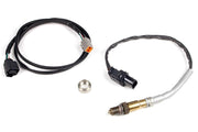
- O2 sensors: the engine has four narrowband sensors, one before and one after the cat on each bank. The ECU can read them, but narrowbands tell you very little for tuning. We fit a WB2 dual channel wideband kit with its LSU 4.9 sensors in the pre-cat bungs. A 22 mm wrench or O2 socket gets the old ones out.
Injectors
The factory injectors flow 260 cc/min, measured held fully open. If your fuel system runs a fixed pressure that isn't referenced to manifold pressure, as many returnless systems do, map injector flow against manifold pressure or your fueling will drift as boost and vacuum change. Accurate dead time data matters just as much, because it covers the time lost while the injector opens and closes.
Dash and CAN
The factory cluster gets its coolant temperature over CAN, so plan for that when you configure the ECU if you want the gauge to keep working.
Base maps
Haltech base maps exist for the Elite adaptor harness setup. Import the map into the ECU rather than opening it as a replacement file, then check trigger, firing order and sensor settings against your engine before the first crank. Our base map basics article explains what a base map is and isn't.
Troubleshooting
| Symptom | Usually |
|---|---|
| Cranks but no sync | Crank reluctor wired backward, or wrong trigger setup for the Subaru pattern |
| Temperature reads wildly wrong | AVI pullup not enabled and no external 1k pullup fitted |
| Coolant gauge dead on the dash | The gauge needs its CAN data |
| Rough idle on a Series 1 | Idle valve not set as BAC 2-wire, or wired to the wrong pin |
| AFR changes with boost despite a stable tune | Returnless fuel system with flow not mapped against manifold pressure |
EZ30D FAQ
Can I keep the factory knock sensors?
Yes. The Elite 2500 reads both, so you keep knock monitoring from both factory sensors.
Do I need a wideband?
For tuning, yes. The factory sensors are narrowband and only tell you rich or lean of stoichiometric.
Can I get the pinout and factory ECU diagrams?
Need this diagram? Ask us and we'll send it over with advice for your build. You'll also find related guides on the EJ25 and EJ20 pages.