Coyote at a glance
Ford's Coyote grew out of the 4.6L Modular V8, but it is not just a bored-out Modular. It uses a different firing order and a long list of improvements, including twin overhead cams per bank with variable timing on every camshaft.
| Spec | Value |
|---|---|
| Layout | V8, DOHC per bank |
| Displacement | 302.1 ci (4951 cc) |
| Firing order | 1-5-4-8-6-3-7-2 |
| Cylinder numbering (viewed from the front) | Left bank 1-4, right bank 5-8 |
| Factory injector flow | 380 cc/min |
Which Coyote do you have?
- Gen 1: 11.0:1 compression, Ti-VCT on intake and exhaust cams, 7000 rpm redline.
- Miami: the Australian supercharged version with a Harrop-Eaton blower and stronger internals, found in the FPV GT and FG-X XR8.
- Gen 3 (2018 on): 12.0:1 compression, combined direct and port injection, a larger 5035 cc bore, new cams, valves and intake, and a 7500 rpm limit. Haltech does not support the Gen 3. If you have one, talk to us before buying anything.
Ford's own vehicle CAN protocol on these cars isn't supported by Haltech, so plan on wiring the engine sensors directly rather than reading them off the factory network.
ECU and harness options
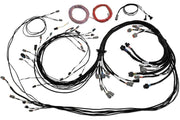
Haltech's Coyote documentation lists the Elite 2500 as the supported ECU, and there are ready-made terminated engine harness kits so you aren't building the loom from scratch. The cam solenoid connector changed during production, so the kits come in early and late versions:
- Elite 2500 + Coyote early cam solenoid terminated harness kit
- Elite 2500 + Coyote late cam solenoid terminated harness kit
- Elite 2500 T early and Elite 2500 T late versions if you need the extra transmission control of the T model
Base maps for these terminated harnesses install with the ESP software, and they already have the triggers, cam control outputs and sensor inputs set up to match the loom. That is the fastest way to a first start. See our Elite 2500 overview for what the ECU itself offers.
Crank and cam triggers
The crank trigger wheel is a plate sandwiched between the crankshaft and flywheel with a 36-1 pattern (36 tooth positions, one missing). It's read by a reluctor sensor mounted at the back of the block between the flywheel and the engine. Each of the four camshafts has its own Hall effect sensor at the rear of the head, reading a 7-tooth wheel: four teeth spaced 90 degrees apart, with three of them carrying an extra tooth beside them. The Bank 1 intake cam sensor is the one used as the Home (sync) signal.
| Sensor and function | Sensor pin | Haltech trigger/home lead |
|---|---|---|
| Crank reluctor, positive | 2 | Trigger 4-core, Yellow |
| Crank reluctor, negative | 1 | Trigger 4-core, Green |
| Bank 1 intake cam, supply | 1 | Home 4-core, Red (12V switched) |
| Bank 1 intake cam, signal | 2 | Home 4-core, Yellow (Home +) |
| Bank 1 intake cam, ground | 3 | Home 4-core, Blue (signal ground) |
The other three cam sensors are wired to spare SPI inputs. Configure them as Hall effect, falling edge, with the pull-up enabled. If you're checking a new install, our crank and cam sensor checks walk through confirming a clean signal.
Ignition: use an igniter
Coyote coils have no built-in igniter. Driving them directly from ECU ignition outputs can damage the ECU. They need an external igniter module between the ECU and the coils.
We use an HPI8 eight-channel igniter on these engines, one channel per coil. Each coil has a three-pin connector: pin 1 is the trigger signal coming from the igniter, pin 2 is unused and pin 3 is 12V switched. If you are building your own coil sub-harness, the Coyote Gen 2 coil plug and pin set saves hunting for connectors. Set dwell from the igniter and coil data, and see our dwell time guide for how dwell is mapped.
Drive by wire throttle and pedal
The Coyote uses a single electronic throttle body, which also handles idle speed, so there's no separate idle valve to wire. Throttle body connections:
| Function | Throttle body pin | Haltech wire |
|---|---|---|
| Motor +/- | 2 and 1 | DBW 1 (Brown/Black) to pin 2, DBW 2 (Brown/Red) to pin 1 |
| 5V sensor supply | 5 | 5V+ (Orange) |
| Sensor ground | 4 | Signal Ground (Black/White) |
| TPS 1 | 3 | AVI-2 (Orange/Black) |
| TPS 2 | 6 | AVI-3 (Orange/Red) |
The matching accelerator pedal is Ford Performance part BR3Z-9F836-D. It has two independent tracks, each with its own supply and ground:
| Function | Pedal pins | Haltech wire |
|---|---|---|
| 5V supply (both tracks) | 1 and 6 | 5V+ (Orange) |
| Ground (both tracks) | 3 and 4 | Signal Ground (Black/White) |
| APP 1 | 2 | AVI-4 (Orange/Yellow) |
| APP 2 | 5 | AVI-5 (Orange/Green) |
Calibrate both throttle and pedal before the first start. Our Elite drive by wire article covers the setup and safety checks.
Ti-VCT cam control
Ford calls it Ti-VCT: all four camshafts are independently phased, each with an oil control solenoid and its own position sensor. Direction matters when you set up targets. The intake cams rest fully retarded and the ECU advances them, while the exhaust cams rest fully advanced and the ECU retards them. That's the same convention as most variable cam engines.
Each solenoid gets 12V switched power on one side and an ECU output on the other. Any spare output will work, but the terminated harness base map uses the stepper outputs, with Active State and Drive Type both set to Low. Remember the early and late connector difference when ordering parts or building a loom. For tuning the cam targets, see cam control on the Elite.
Supporting sensors
MAP
The Coyote doesn't come with a MAP sensor. The ECU's internal sensor is fine for naturally aspirated and moderate boost builds, and for higher boost, fit an external sensor such as a 5 bar TI MAP sensor on a spare AVI. Some Ford Performance crate engines have no vacuum port at all, so plan on adding a fitting to the intake close to the throttle body.
Coolant (cylinder head) temperature
Ford uses a cylinder head temperature sensor. It's a two-wire thermistor that isn't polarity sensitive: one pin to a spare AVI, the other to signal ground. Use an AVI with a selectable pull-up, or add a 1k resistor from the signal to 5V.
Air temperature and MAF
The factory air temp sensor lives inside the MAF in the airbox. Most Haltech builds delete the MAF, and if you do, add a separate intake air temperature sensor. If you keep it, MAF signal (pin 5) goes to a spare AVI, air temp signal (pin 2) to a spare AVI with pull-up, pin 4 to signal ground, and pin 3 takes 12V switched.
Knock
There are two knock sensors on a six-pin connector: pin 5 is knock 1, pin 3 is knock 2, and pins 2 and 4 are signal grounds. Pins 1 and 6 aren't used. See knock detection for setup.
Alternator
The Coyote alternator is ECU controlled. It needs a duty signal to set charging voltage: pin 1 to 12V switched (Grey/Red) and pin 2 to a duty output, DPO-3 (Violet/Red) on the terminated harness. Pin 3 is unused. Configure it with alternator control, otherwise it may not charge correctly.
Oxygen sensors and vehicle speed
We strongly recommend a WB2 dual channel wideband kit, with its LSU 4.9 sensors replacing the factory pre-cat sensors (a 22 mm wrench or socket fits). Vehicle speed comes over the factory CAN network on these cars, which Haltech doesn't read, so add a dedicated speed sensor if you need speed-based functions.
Injector data
Stock Coyote injectors flow 380 cc/min, measured held fully open. Many Coyote fuel systems are returnless, with rail pressure that doesn't follow manifold pressure. In that case the effective flow changes with manifold pressure, so map injector flow against MAP for accurate fueling. Dead time is the part of every pulse where the injector isn't delivering full flow: opening, closing and the partial-flow transitions. Getting it right matters most at idle and cruise. Read more in injector dead time.
Coyote FAQ
Can I run a Gen 3 Coyote on Haltech?
No. Haltech lists the 2018-on Gen 3, with its combined direct and port injection, as not supported, so check which generation you have before buying parts.
Do I need the MAF?
No. Most of our Coyote builds run speed density on MAP. Just remember the air temp sensor goes with the MAF, so add one.
Early or late harness?
Look at the cam solenoid connectors on your engine. If you're unsure, send us photos through our contact page and we'll confirm before you order. For a full swap plan, book a free consultation.