Why log wastegate pressure?
A wastegate opens or stays shut based on the pressure acting on its diaphragm, not directly on manifold boost. With a boost control solenoid in the line, or a CO2 system feeding the gate, those two numbers can be very different. The Wastegate Pressure Sensor function in ESP lets the Elite read and log the pressure actually delivered to the diaphragm.
That's useful in a few situations:
- CO2 and dual-port setups, where you need to know exactly how much pressure is holding the gate shut or pushing it open. See CO2 boost control wiring.
- Diagnosing boost problems. If boost creeps, spikes or won't reach target, seeing wastegate pressure next to manifold pressure and solenoid duty in a log usually points straight at the cause: a leaking line, a tired solenoid or a gate that's too small.
- Consistency on race cars, where you want proof that the gate is seeing the same pressure every pass.
Picking a sensor
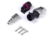
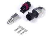
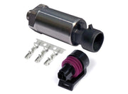
Any linear pressure sensor with a known calibration will do, as long as its range comfortably covers the highest pressure your wastegate line will see. Haltech's options include the 150 psi TI sensor, the 250 psi TI sensor if you need more range, and the 150 psi motorsport sensor.
Wiring tab: choosing the input
An AVI (analog voltage input) is the preferred choice. If you've run out of AVIs, an SPI can read the sensor instead.
| Setting | What it does | Our advice |
|---|---|---|
| AVI pullup | Switches in a 1k resistor to 5V on the input | Leave it off for a powered 3-wire pressure sensor |
| SPI Sensor Type | Tells the SPI what kind of signal to expect | Set to Hall Effect whenever the SPI is reading an analog sensor |
| SPI pullup | Switches in a weak 10k resistor to 5V | Off for a powered sensor, the same as on an AVI |
The pullup rule is the same everywhere in ESP. Two-wire temperature sensors need one. Sensors with their own power supply, like a wastegate pressure sensor, don't. And if the sensor signal is shared with another ECU, as in some piggyback installs, the other ECU usually already provides the pullup, so switch it off on the Elite.
Calibration tab
This is where ESP learns how to turn the sensor's voltage into pressure. Several calibrations ship with ESP. Click the yellow Open icon to load one. If your sensor isn't in the list, build a custom calibration from the manufacturer's voltage-versus-pressure data, then click the blue Disk icon to save it so you can reuse it on the next car.
A quick sanity check: with the engine off and no pressure in the line, the reading should match ambient. That means near zero for a gauge-referenced calibration, or close to your baro reading for an absolute one. If it's way off, the calibration or the input selection is wrong.
Display tab
- Warning Maximum: any gauge showing wastegate pressure flashes red above this value. Set it just above the highest pressure you expect in normal use, so a stuck solenoid or regulator fault is impossible to miss.
- Display Minimum and Display Maximum: the range shown on gauges in ESP. These only change the gauge scale, not the sensor reading.
Diagnostics tab
These two settings catch wiring faults, and they only appear when the input type is analog voltage. Both are disabled by default.
| Setting | Sets this code | When |
|---|---|---|
| Raw Min | P1350 | Sensor voltage drops below the value you enter |
| Raw Max | P1351 | Sensor voltage rises above the value you enter |
A healthy sensor never sits right at 0V or 5V, so a reading pinned at either end almost always means a short or an open circuit. We set Raw Min a little under the sensor's lowest real output and Raw Max a little over its highest. If Engine Protection is active, you can also give each code a DTC severity so the ECU reacts rather than just logging it. The full list of codes is in the DTC index.
Troubleshooting
| Symptom | Usually |
|---|---|
| Reading pinned high | Signal shorted to 5V, or a broken sensor ground |
| Reading high or drifts with a sensor that checks out | Pullup left enabled on a powered sensor |
| Reading stuck at zero | No 5V supply, a broken signal wire, or the wrong input selected |
| Reading plausible but offset | Wrong calibration loaded, or a gauge-type sensor used with an absolute calibration |
| P1350 or P1351 set | Wiring fault, or Raw Min/Max set too close to the sensor's normal range |
Once the sensor reads correctly, pair it with your boost control setup and the boost pressure sensor if you run one, and log all three together.