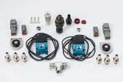
This Elite wiring diagram shows how to connect a CO2 boost control system, such as the CO2 boost control dual solenoid and pressure sensor kit. Instead of relying on manifold pressure alone, a CO2 system feeds regulated gas to the wastegate, which gives drag cars very precise and repeatable boost. You'll want the diagram any time you're installing or fault-finding one of these kits.
What to check
- Both solenoids land on the outputs you assign in ESP, and their power and ground match the diagram pin for pin.
- The pressure sensor is powered and grounded as shown, and reads a sensible value in ESP with the system at rest.
- Grounds and fusing follow the rest of your installation. See the fuseblock assembly and wire color legend.
Once wired, set up the control strategy in boost control.
Need this diagram? Ask us and we'll send it over with advice for your build.