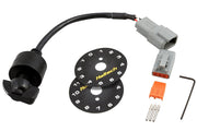
What a rotary trim module is for
The 12 position rotary trim module is a dash-mounted selector knob. The ECU reads which position it's in, and you can then use that position as an axis in a target table or a trim table. That turns one knob into a driver-adjustable setting for whatever you point it at.
Common uses we set up:
- Boost: each position selects a different boost target, or trims boost down from the maximum. See boost control.
- Torque management and traction: positions step the amount of slip allowed, so the driver can dial it in as the track changes. See torque management.
- Fuel or ignition trims: a small, controlled adjustment for a different fuel or a hot day.
Calibrating it in NSP
The ECU sees the knob as a voltage on an analog input, so it needs a calibration that translates each voltage into a switch position. On the Rotary Trim Module node you can either load one or type it in.
For a module bought from Haltech, the easy way is the Load from File button. There are two ready-made calibration files, and you pick the one that matches the sticker on your knob:
| Calibration file | Positions read as | Good for |
|---|---|---|
| 0 to 12 | Numbered steps counting up | Selecting settings, like boost levels or traction steps |
| -5 to 6 | Negative, zero and positive steps | Trims either side of a baseline, like more or less fuel |
If you've built your own calibration, the Save to File button stores it so you can reuse it on another car or restore it later.
Wiring
The module uses an analog voltage input. Any spare AVI will work, and you assign it on the wiring node for the trim module. Haltech's setup notes recommend disabling the pullup, and we always do: turn the AVI's pullup off. The calibration expects a specific voltage for each position, and an extra pullup on the input can shift those levels so positions read wrong.
Using it in a table
Once the input is calibrated, the rotary trim position shows up as a channel you can use as a table axis. A typical boost setup puts the trim position on one axis and gear or RPM on the other, so each knob position gives a complete boost strategy. Test every position on the ground first, and set the lowest or zero position to your safest setting in case the knob gets bumped.
Troubleshooting
| Symptom | Usually |
|---|---|
| Positions read one step off, or jump between two | AVI pullup still enabled, or wrong calibration file for the sticker |
| Position always reads the same | Wrong AVI assigned, or no supply or ground at the module |
| Numbers on the knob don't match NSP | Loaded the 0 to 12 file with a -5 to 6 sticker, or the reverse |
More on the hardware is in our rotary trim modules article, or ask us for help choosing what to put on the knob.