What this harness is for
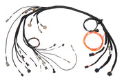
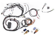
The Nexus R3 Nissan RB terminated harness (HT-186401) plugs straight into a Nexus R3 VCU and is built for engine conversions using the RB20DET, RB25DET, RB25DET Neo, RB26DETT and RB30E. Both ends are terminated: the engine bay side lands on the factory and Haltech sensors, and the cabin side gives you tidy connectors for the key switch, pedal, gauges and spare wiring. The R3 also takes over jobs that used to need their own relays, like the starter, fuel pump and thermofan feeds.
If you are building a Barra instead, the layout is similar and covered in our Nexus R3 Barra harness guide. Running an Elite instead of a Nexus? Look at the Elite 2000/2500 RB terminated harness or the twin cam version with CAS harness.
Before you plug anything in
Nexus units can talk to NSP over the USB cable with no +12V supply at all. Use that. Load or build your tune, set the ignition mode, dwell and injector setup, and check every output assignment before the VCU ever sees battery power. Powering up with the wrong coil or injector settings is the fastest way to cook a coil, an injector driver or both.
The harness does not ground the engine, and neither does the coil ground ring described below. Run a proper engine-to-battery ground strap. Also keep fuel and wiring away from exhaust heat, disconnect the battery while you work, check for fuel leaks when you are done, and never disconnect or charge the battery with the engine running, because that can feed the VCU an unregulated supply.
What comes in the kit
- The main terminated harness (HT-186401)
- Two CAS adaptors: HT-186142 for RB25/RB26 and HT-186141 for RB30
- Two cable throttle sub-harnesses: HT-186164 for RB25/RB26 style connectors and HT-186167 for early RB30
- Two alternator adaptors: HT-186125 (Yazaki 2-pin) and HT-186126 (EV1 2-pin)
- A cabin adaptor harness (HT-186130)
- Mating connectors and pins for the boost solenoid, transmission breakout and spare I/O
Sold separately, and chosen to suit your engine:
| Part | Use it when |
|---|---|
| HT-186010 injector harness | Your injectors use Sumitomo (Denso) plugs |
| HT-186004 injector harness | Your injectors use Timer (EV1) plugs |
| HT-186007 injector harness | Your injectors use GT150 (USCAR/EV6) plugs |
| HT-186063 ignition harness | You are running R35 coil-on-plug ignition |
| HT-186162 DBW sub-harness | You are converting to a Bosch electronic throttle |
Power, ignition feed and starting
Battery connection
The R3 is powered through two SurLok terminals, and both must stay connected to the battery at all times. Positive (red) goes to battery positive through a fuse; a 150 A fuse is the recommendation. Negative (black) goes straight to battery negative. Use the supplied red and black SurLok connectors with 4 AWG cable, which you will need to supply. Spare SurLok connectors are available if you need them.
Ignition switch input
The pink wire, found at the cabin spare I/O connector alongside the pedal connector, is what wakes the VCU. Feed it from a switched +12V source that stays live while cranking. Many key switches drop the accessory circuit in the Start position, and if you pick that one the VCU will blink off every time you crank. See Ignition Switch for the software side.
Starter control
A high-current output wire (up to 25 A, driven by the HCO 25A 1 pin) ends in a spade terminal that goes straight onto the starter solenoid. Assign that pin to starter control in NSP. The VCU also needs to know when the driver is asking to crank, so there is a white wire in the cabin connector on AVI 1 (pin 8) for the starter signal from the key. You can move that request to any spare AVI or SPI, or to a CAN keypad button. Setup details are in Starter Motor.
Engine sensors
Cam angle sensor
Skyline RB engines (R32, R33 and R34) use an optical CAS on the front of the exhaust cam. It gives the VCU both speed and position, so there is no separate crank sensor. The catch is that R32/R33 and R34 sensors do not share a pinout. That is why the HT-186142 adaptor comes with its wires pinned but not yet inserted into the CAS connector: you pin it to suit your sensor. The RB30 is different again, with its optical sensor inside the distributor, and the HT-186141 adaptor plugs directly into it. Trigger details for the single cam are in RB30 trigger information.
The optical CAS grounds itself through its housing to the engine. Leave its ground pin off the sensor ground circuit. Tying them together can skew the readings on your other sensors.
MAP, temperatures and pressures
- MAP: the R3 has an onboard 4 bar sensor, good for about 43 psi of boost. Run a vacuum line from its barb to the intake manifold, or tee into the fuel pressure regulator reference line. Planning more boost than that? Wire an external sensor such as the 7 bar TI MAP sensor to the engine bay spare connector. The factory AFM is not needed; load comes from manifold pressure.
- Coolant and air temperature: plugs are provided for the factory 2-pin coolant sensor and a Haltech air temp sensor (HT-010206). Both feed the VE fuel model, so they are not optional.
- Oil and fuel pressure: Delphi 3-pin plugs match Haltech pressure sensors like the 150 psi TI sensor. The engine will run without them, but we fit them to every build because they drive fuel pressure compensation and engine protection.
- Factory gauge senders: the stock oil pressure and coolant temperature gauge senders are wired through to cabin connector pins 19 and 18. The VCU does not read them; they are there so you can keep analog gauges.
Wideband, knock and flex
A DTM-6 plug connects to a Haltech wideband hardware pack, either the Bosch LSU 4.9 pack or the NTK pack, and the controller is built into the R3. With it you get closed loop fueling and lean protection. Two connectors suit Bosch knock sensors, which are broadband units that suit modified engines better than the factory parts. There is also a plug for a flex fuel sensor if you want the tune to follow ethanol content.
Injectors and ignition
Injectors connect through a breakout plug, so you choose the sub-harness that matches your injector connectors, and every plug on it is labeled by cylinder. Ignition works the same way: the breakout suits the HT-186063 harness for R35 coils, which removes the external igniter used on early RBs. The breakout can also be wired to another coil and igniter combination if you have one in mind.
A 10 mm ring terminal provides the coil ground and bolts to the cylinder head. Again, it is for the coils only, not a substitute for the engine ground strap.
Throttle: cable or drive by wire
The throttle breakout takes either a cable throttle sub-harness (both included) or the Bosch DBW sub-harness.
- HT-186164: for twin cam engines and engines with the later connector style. It covers the AAC idle valve, FICD and TPS, and has a flying lead on the TPS branch for alternative pinouts.
- HT-186167: for RB30s with the early connector style.
Whichever you use, the VCU needs a variable TPS. Some RBs have a TPS that is only an idle and full-throttle switch, and some early RB30 units combine a switch with a variable track on two connectors. Test yours with a meter. If it only switches, swap it for a variable sensor from another RB or a suitable aftermarket unit.
Going to DBW? Plug in the HT-186162 sub-harness at the throttle and wire your pedal to the 6-pin DTM connector built into the cabin connector. Pin 21 of the cabin connector is for a brake switch or brake light signal that goes to +12V when the pedal is pressed, which the DBW strategy uses. Our DBW troubleshooting guide is worth a read before first start.
Outputs the R3 drives directly
| Circuit | Wire or connector | What we use it for |
|---|---|---|
| Thermofan | Red/Orange 10 AWG | Fan on/off temperatures, A/C request, switching off above a set road speed (needs a speed sensor) |
| Fuel pump | Red/Yellow 10 AWG | Prime at key-on, and shut off when the VCU loses RPM |
| Alternator | 2-pin DTM plus Yazaki or EV1 adaptor | Switched +12V excite, via a 470 ohm resistor that stands in for the charge light |
| Boost solenoid | 2-pin DTM | A 3-port solenoid like the HT-020400 for stable control |
| VCT solenoid | Plug at the solenoid behind the timing cover | Tuned with Cam Control in NSP, or repurposed if your engine has no VCT |
Because the fan and pump are powered straight from the VCU's high-current outputs, you can skip the separate relays those circuits would otherwise need. Setup is in Thermo Fan and Fuel Pump.
CAN and spare I/O
There is a 4-pin DTM CAN connector at each end of the loom for Haltech dashes, keypads and PDMs. Running more devices than ports? Add a CAN hub. For extra sensors, switches, relays or warning lights, the cabin end has a 26-pin connector labeled Cabin, and the engine bay end has a 12-pin DTM labeled Spare. Mating plugs for both are in the kit.
Need the harness pinout diagrams or the CAS pin tables? Ask us and we'll send them over with advice for your build.
Common problems on RB installs
| Symptom | Usually |
|---|---|
| VCU drops out while cranking | Pink wire is on an accessory feed that dies in Start |
| No RPM signal | CAS adaptor pinned for the wrong model (R32/R33 vs R34) |
| Other sensors reading oddly | CAS ground pin tied into the sensor ground circuit |
| TPS stuck at 0% or 100% | Switch-type TPS still fitted |
| Erratic sensor readings | Missing engine-to-battery ground strap |
| Alternator not charging | Excite plug not connected, or the adaptor does not match your alternator |
FAQ
Can I keep the factory AFM?
You don't need it. The R3 calculates load from manifold pressure, so most RB conversions drop the AFM entirely.
Does it work on a non-VCT RB?
Yes. The VCT connector simply goes unused, and its output can be reassigned to something else.
Want a second set of eyes on your plan? Book a free 30-minute consultation.