What "standalone" means for the iC-7
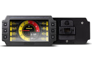
Most iC-7 dashes get their data over CAN from a Haltech ECU. A standalone install flips that around: the dash has its own wiring harness and reads sensors, switches and signals itself. That's what makes it such a good upgrade for older vehicles with a carburetor or mechanical injection, where there's no ECU to talk to. You get a 7 inch color screen, a digital fuel gauge, warnings and layouts you can change, and you can still add Haltech CAN modules later.
If you're starting from scratch, the iC-7 standalone classic kit bundles the dash with what you need for this type of install. The harness is also sold on its own as the semi-terminated standalone harness, and there's an iC-7 sensor pack if you want matched sensors.
What the standalone harness gives you
| Connection | How it's terminated | Typical use |
|---|---|---|
| AVIP 1 (OIL PRESS) | 3-pin Delphi plug | Haltech 0-150 psi pressure sensor, set up as oil pressure |
| AVIP 2 (FUEL PRESS) | 3-pin Delphi plug | Haltech 0-150 psi pressure sensor, set up as fuel pressure |
| AVIP 3 (CTS) | DTM-2 plug | Haltech coolant temperature sensor |
| AVIP 4 (FUEL LVL) | Flying lead plus an in-line DTM-2 | Your existing fuel level sender |
| SPEED IN | Harness pin 33 | GPS speed module or an OEM speed sensor |
| TACHO IN | Unterminated flying lead | Engine speed from a coil, factory ECU or harness tach wire |
| CAN | CAN port | Haltech CAN devices such as TMS-4, WB1/WB2 and TCA modules |
The AVIP inputs read 0 to 5 volts. Oil, fuel pressure, coolant and air temperature and fuel level all have ready-made calibrations, and anything else can go in as a custom calibration.
Plan your sensor locations first
Before any wire gets cut, work out where each sensor will live. On most classic engines the factory gauge sender ports are the obvious first choice, and a little research on your engine usually turns them up. Things we check on every install:
- Thread size. Haltech's pressure sensors use a 1/8" NPT fitting. If the port is bigger, use a proper reducer rather than forcing something that almost fits. A common example is a 3/8" NPT port on the thermostat housing or water neck, stepped down to 1/8" NPT for the coolant sensor.
- Sealing. Clean the threads and use a suitable thread sealant. Don't wrap sensor threads in so much tape that the sensor body can't ground or seat.
- Fuel pressure. On a carbureted car a brass tee in the feed line just ahead of the carb gives you a 1/8" NPT port for the sensor. A 150 psi sensor reads a 5-7 psi carb system fine, and it also leaves plenty of range for mechanical injection, which runs far higher pressures.
- Heat and vibration. Keep sensor pigtails away from exhaust manifolds and give them a little slack so engine movement doesn't pull on the connector.
For the pressure inputs, a sensor like the 150 psi fuel/oil pressure sensor matches the default calibration. For coolant, the 1/8" NPT coolant temp sensor is the easy fit.
Optional CAN add-ons worth doing while the car is up
The standalone iC-7 still talks CAN, so Haltech's modules plug straight in with a CAN cable:
- Wideband O2. A WB1 or WB2 gives you real air/fuel ratio on the dash, which is gold when you're jetting a carb or setting up mechanical injection. On a V8 with dual exhaust, a WB2 lets you watch each bank. Put the sensor bung roughly 6-10" downstream of where a bank's pipes merge, which on most headers means just after the collector. See our WB1 and WB2 guide for more.
- Tire pressure. The TMS-4 is available with internal sensors or external sensors. External caps are the quickest to fit and swap between wheel sets, and no calibration is needed once the module is on the CAN bus. The TMS-4 quick start covers the details.
- Exhaust gas temperature. A TCA thermocouple amplifier such as the TCA2 adds EGT channels the same way.
We like to mount these modules on the firewall where the CAN cables and sensor leads are easy to reach and the modules stay clear of heat.
Fuel level sender
The FUEL LVL input has a flying lead with an in-line DTM-2 connector. Build your sender wiring to that plug so the tank can come out later without cutting anything. While you're under the car, make sure the sender has a good ground, since a poor ground shows up as a jumpy or wrong fuel reading.
Speed and tach
Vehicle speed
Plenty of classics still run a mechanical speedometer cable, and there's no clean way to feed that to a digital dash. The GPS speed input module is the simplest fix. It connects to the iC-7 harness with one cable, needs no calibration beyond ticking a box in ICC, and drives the speedometer, odometer and trip meter in mph or km/h.
If your vehicle already has an electronic speed sensor, you can use that instead. Here's how we work out its pulse rate when we don't know it:
- Wire the sensor signal to SPEED IN (pin 33), and make sure the sensor and dash share power and ground.
- In ICC, open the speed channel settings and untick the option for the Haltech GPS module.
- Put the Speed Pulse Rate channel on a spare gauge.
- Drive at a steady 25 mph (40 km/h), checked against a GPS app or similar, not the old speedometer.
- Read the Speed Pulse Rate value, enter it in the pulse rate (PPM) box and click Apply.
If you already know your sensor's PPM, skip the drive and enter it directly.
Tachometer
TACHO IN is a flying lead, so it splices into whatever tach signal your engine has: a coil negative tach terminal, a distributor or ignition box tach output, or a factory ECU tach wire. Many older cars have a tach provision at the coil even if the original cluster never showed RPM. In ICC, click the tachometer on the dash layout, set the minimum and maximum RPM for the gauge, pick your engine type from the Engine Type list and click Apply. If the RPM reads double or half, the engine type is usually the culprit.
Cabin wiring
Pull the factory cluster and study its plugs. They usually carry most of what you need: turn signals, high beam, parking lights, the fuel sender wire and switched power. A key detail is that the iC-7's switch-style inputs are positive trigger, meaning they read an input as on when it sees 12 volts. The two exceptions are the fuel sender and the handbrake input. Check your vehicle's circuits before you connect, because some older lamp circuits switch the ground side instead.
Rather than a pile of butt connectors behind the dash, we prefer a small multi-pin connector (an 8-pin Deutsch works well) between the vehicle wiring and the dash harness. It keeps things tidy and lets the dash come out in minutes. Take switched +12 V and ground from your fuse block, not from a random lighting circuit. Our crimping guide and grounding guide apply here just as much as they do to an ECU.
Mounting the display
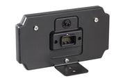
Every classic dash is different. The iC-7 moulded panel mount is a good starting point for a custom bezel: trim it to fit the factory cluster opening, let the cables pass through behind the display, and use the original cluster mounting points where you can. If you'd rather not cut anything, the standard dash mount sits on top of the dash.
Setting it up in ICC
- Connect the dash to your laptop with the USB cable and open ICC.
- From the main screen, choose Load Defaults and select Standalone. This loads the standalone firmware setup and switches every input to Direct mode, so the dash reads its own harness instead of waiting for ECU data.
- Configure the speed and tach channels as described above.
- Check the pressure and temperature channels (below), then calibrate the fuel level.
Oil and fuel pressure channels
AVIP 1 and AVIP 2 ship set up for Haltech's 0-150 psi sensors and labeled Oil Pressure and Fuel Pressure. To use a different sensor, open Dash Settings, then Channels, select the AVIP sensor value, rename it if you want, and open Input Calibration. You can choose another sensor from the list or enter a custom one. Most pressure transducers are 0-5 V, but not all, so get the real voltage-to-pressure data from the sensor maker before entering a custom calibration.
Calibrating the fuel gauge
Go to Dash Settings, Channel Settings, choose AVIP 4 Sensor Value and open Input Calibration. The list includes common sender resistance ranges, so if yours is there, select it and apply. If it isn't, choose Custom and calibrate it yourself. With the sender connected to the dash, measure the voltage across the sender at the float's lowest and highest positions and enter them at 0 and 100. More points give a more accurate gauge, so if you can, measure all eight. If you only enter the ends, the software fills in the gaps.
Troubleshooting
| Symptom | Usually |
|---|---|
| Dash shows no sensor data at all | Standalone defaults not loaded, so inputs aren't in Direct mode |
| RPM reads double or half | Wrong Engine Type selected for the tach channel |
| Speed wrong with an OEM sensor | Pulse rate not calibrated, or the GPS box still ticked |
| Indicator or light warnings never come on | Circuit switches ground, but the input expects positive trigger |
| Fuel gauge jumps or reads backward | Poor sender ground, or empty and full voltages swapped |
| Pressure reads off by a fixed amount | Sensor calibration doesn't match the sensor fitted |
FAQ
Can I add a Haltech ECU later?
Yes. The iC-7 is the same dash either way. When an ECU goes in, the dash can take most of its data over CAN instead, and you reconfigure the channels in ICC.
Does a standalone iC-7 work with a carburetor?
That's exactly what it's for. Nothing about it needs fuel injection. Pair it with a wideband and it becomes a real tuning tool for the carb, too.
Where's the pin-by-pin harness diagram?
For vehicle-specific cluster wiring, see our R33 iC-7 wiring guide as an example, or ask us and we'll help map your car's cluster plugs to the iC-7 harness.