Which CA18 this covers
Nissan built several CA18 versions, but the one people put a Haltech on is almost always the turbocharged CA18DET, so that's the engine this guide covers. Any Elite ECU can run it, and for S13 Silvias there's a ready-made option in the Elite 1500 S13 CA18DET plug-in kit.
| Spec | CA18DET |
|---|---|
| Cylinders | 4, inline |
| Displacement | 1809 cc |
| Firing order | 1-3-4-2 |
| Factory injector size | About 370 cc/min |
Early vs late engines
It's worth knowing which one you have before you order parts:
- Early: 4-port intake head, T25 turbo.
- Late: 8-port intake head with a different lower intake manifold and larger diameter head bolts. The 8-port engines are the ones with variable intake runner control (covered below).
The CAS trigger
The crank and cam signals come from one unit, usually called the CAS (crank angle sensor), bolted to the front of the head and turned by the exhaust camshaft. Inside is a slotted disc read by two optical sensors. The outer ring has 360 slots. The inner ring has 4, and they're different widths. The ECU counts how many of the fine 360x pulses happen during each of the 4x pulses, and because each window is a different size, that count tells it which cylinder is coming up.
| What it carries | CAS pin | Goes to |
|---|---|---|
| Ground | A | Trigger 4-core, blue |
| Switched 12V supply | B | Trigger 4-core, red |
| 360 slot signal | C | Home 4-core, yellow (Home+) |
| 4 slot signal | D | Trigger 4-core, yellow (Trigger+) |
One-cable trick for universal harnesses
An optical CAS doesn't use Trigger-, and from the Home cable it only needs Home+. So with one pin move at the ECU plug you can feed the whole CAS from the Trigger 4-core and skip the Home cable:
| ECU | Pull the yellow wire and insulate it | Move the green wire |
|---|---|---|
| Elite 550 / 750 / 950 | A32 | From A33 into A32 |
| Elite 1000 / 1500 / 2000 / 2500 | B2 | From B5 into B2 |
The green wire now carries the 360x signal to the Home+ pin, all inside the Trigger cable. The SR20 uses a very similar optical CAS, so if you've done one, you've done both.
Ignition
The very earliest engines used waste spark (one coil for each pair of cylinders). Later engines went to direct fire with a coil on every plug. Both use an external igniter, and both are set up in the software as constant charge with a falling edge.
Early waste spark
- Igniter pin 1 (cylinders 1 and 4) to Ignition Output 1.
- Igniter pin 2 (cylinders 2 and 3) to Ignition Output 2.
Late direct fire
The igniter module takes four trigger signals, one per cylinder. Note the pin letters don't run in cylinder order:
| Haltech output | Igniter pin | Cylinder |
|---|---|---|
| Ignition Output 1 | D | 1 |
| Ignition Output 2 | F | 2 |
| Ignition Output 3 | C | 3 |
| Ignition Output 4 | E | 4 |
Igniter pin A is its ground to the cylinder head, and pin B isn't used. Each coil has a three-pin plug: the signal from the igniter, switched 12V, and ground to the head.
If the factory igniter is missing or tired, we use a Haltech HPI4 igniter. Follow its own quick start guide for wiring, and set dwell to suit the coils you're running. Our dwell time article explains what too much and too little look like.
Throttle position sensor
The throttle is cable-driven, and the TPS plugs in through a cable connector rather than directly at the sensor body. The wiring is simple:
- Red: 5V supply, to the Haltech orange 5V wire.
- White: signal, to any spare AVI.
- Black: ground, to Haltech signal ground (black/white).
Idle control
There are two solenoids on the idle air valve. The big one, which Nissan calls the IACV-AAC, is the one the ECU controls with a duty signal through a single output. The smaller IACV-FICD simply adds air when the A/C is on: it has a permanent ground and gets 12V from the A/C relay, so it never connects to the Haltech. Tune the AAC under idle control.
Variable intake runners (8-port engines)
On the 8-port head each cylinder has two intake runners. Below 3800 rpm, butterflies close one of the pair, which speeds up the air in the other runner and sharpens low-speed response. A vacuum actuator moves the butterflies, fed from a vacuum reservoir through a solenoid the ECU switches on or off. On an Elite, that solenoid is driven by the dual intake runner function, and you can move the switchover point if your cam or turbo changes where it's best.
Sensors
| Sensor | Notes |
|---|---|
| MAP | Not fitted from the factory. The ECU's internal sensor is fine for moderate boost. For more boost, fit an external MAP sensor on a spare AVI. |
| Coolant temp | On the intake manifold toward the front. Two wires, either way around: one to a spare AVI, one to signal ground. |
| Air temp | Not fitted. Add a Haltech air temp sensor in the intake, as close to where the MAP reads as you can. Wired like the coolant sensor. |
| Knock | The factory sensor is an old design that fails often and isn't much help on a modified engine. We swap it for a modern donut-style Bosch knock sensor: signal to the knock input, other pin to signal ground. |
| MAF | Usually deleted for speed density. If you keep it: pin 2 switched 12V, pin 3 sensor ground, pin 4 the 0-5V signal to a spare AVI, pin 1 unused. |
For both temperature inputs, use an AVI with its 1k pull-up to 5V switched on. If the input you picked doesn't have a selectable pull-up, fit an external 1k resistor to 5V.
O2 sensor and heater
The stock sensor is a 3-wire heated narrowband. White is the signal, to AVI 1 or AVI 6. Red is heater power from switched 12V. Black is the heater ground, normally to chassis.
Many factory ECUs control the heater by pulsing that ground, and a Haltech can too, using a spare injector or stepper output (see O2 heater). Heaters are commonly 12W or 18W. On an 18W element, keep duty at roughly 50% or less so the output isn't overloaded.
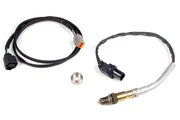
Really though, a narrowband isn't a tuning tool. We recommend a WB1 wideband kit, with its LSU 4.9 sensor going where the factory sensor was. A 22 mm wrench or O2 socket gets the old one out.
Speed signal and factory ECU
The speed sensor is a reluctor type that drives the speedometer directly. The speedometer then outputs a digital Hall-style signal that the ECU reads. The factory ECU lives in the passenger (left-hand) footwell kick panel.
Base maps
Haltech has base maps for the Elite plug-in adaptor harnesses. Import them into the ECU rather than just opening them, so your ECU's own settings are handled properly. A base map gets the engine started. It's not a tune, as we explain in base map basics.
Troubleshooting
| Symptom | Usually |
|---|---|
| RPM while cranking but no sync | 360x and 4x signals swapped, or a pin in the wrong place after the one-cable mod |
| Spark on the wrong cylinders | Direct fire igniter wired in pin order instead of cylinder order |
| Weak spark or misfire under boost | Tired factory igniter or coils, or dwell set for different coils |
| False knock everywhere | Worn factory knock sensor. Replace it before tuning knock control |
| Flat spot near 3800 rpm | Intake runner solenoid not switching, or a vacuum leak at the actuator |
CA18 FAQ
Do I need an external MAP sensor?
Only if you plan to run more boost than the internal sensor can read. Check the rating of the internal sensor on your ECU against your boost target, and leave some headroom.
Should I keep the variable intake runners?
On a street car, yes. They cost nothing to run and help low-speed response. We tune the switchover point on the dyno.
Is the CA18 wiring similar to other Nissans?
The optical CAS is shared with several engines of that era. Compare with our TB42 guide, or book a free consultation and we'll look at your setup.