

ECU plus PDM

Sold separately

Sold separately
Haltech Nexus R5 VCU (HT-195000)
SKU: HT-195000
Nexus Must-Haves
ECU plus PDM
Sold separately
Sold separately
ECUs always ship FREE with Tuned By Shawn!
Manufacturer Limited Warranty
Haltech Nexus R5 VCU (HT-195000)
Product details
Description
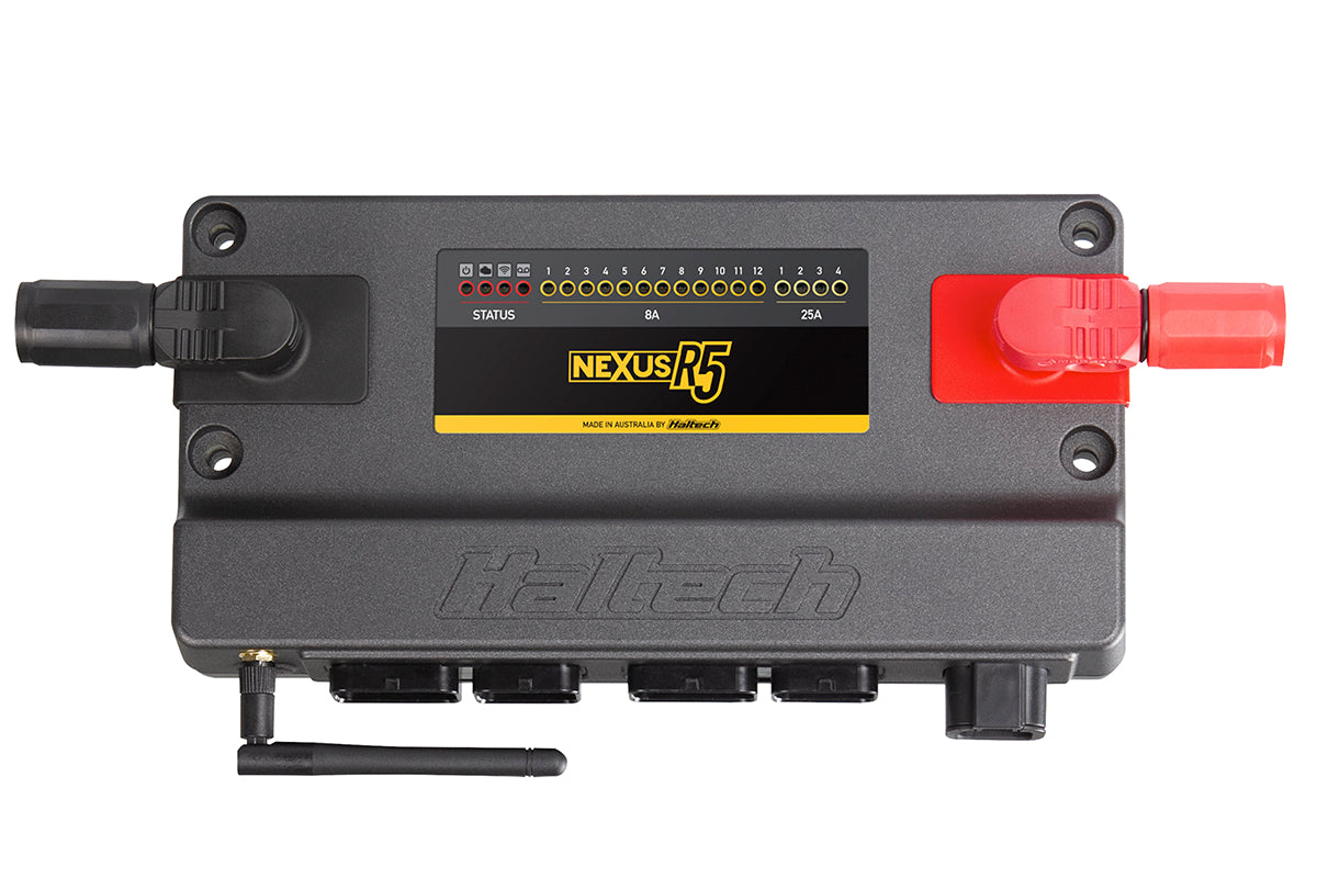
The Haltech Nexus R5 VCU is the core of a serious engine management installation, with the processing power, I/O, and software support to control the engine properly and prove it in data. Racing application where advanced race features, data logging and power management control is required.
What You'll Feel
A car whose entire electrical and engine control layer behaves and gets logged: DBW throttle mapped your way, onboard dual wideband holding closed loop accuracy under boost, and native torque, boost, and traction strategies without add-on boxes.
Features
- Engine management, PDM, data logger, and dual channel wideband controller in one device
- 4 x 25A push-pull PWM outputs and 12 x 8A high side outputs
- 18 peak and hold injector drivers and 12 ignition outputs
- 4 x 8A h-bridge outputs for electronic throttle
- 23 analogue inputs with DBW redundancy
- 2 onboard wideband controllers, 3 CAN ports
The Details
- SKU: HT-195000
Nexus R5 VCU Pinout
Complete pin-by-pin map of all five Nexus R5 VCU connectors. Wire colors are those of the Nexus R5 universal wire-in harness. Main battery power connects via the SurLok terminals, not these connectors.
Connector A
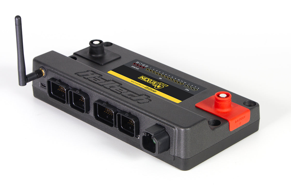
34-pin Superseal, Keyway 1 - injectors 1-8, ignition 1-8, DPO 1-8, HBO, battery ground out and CAN 1.
Looking into the connector on the VCU
| Pin | Function | Harness Wire Color |
|---|---|---|
| A1 | Injector 1 | Blue |
| A2 | Injector 2 | Blue/Black |
| A3 | Injector 3 | Blue/Brown |
| A4 | Injector 4 | Blue/Red |
| A5 | Injector 5 | Blue/Orange |
| A6 | Injector 6 | Blue/Yellow |
| A7 | Injector 7 | Blue/Green |
| A8 | Injector 8 | Blue/Violet |
| A9 | DPO 1 | Violet/Black |
| A10 | Battery Ground Out | Black |
| A11 | Battery Ground Out | Black |
| A12 | DPO 2 | Violet/Brown |
| A13 | Ignition Switch Input | Pink |
| A14 | DPO 3 | Violet/Red |
| A15 | DPO 4 | Violet/Orange |
| A16 | DPO 5 | Violet/Yellow |
| A17 | DPO 6 | Violet/Green |
| A18 | DPO 7 | Black/Yellow |
| A19 | HBO 1 | Brown/Black |
| A20 | HBO 2 | Brown/Red |
| A21 | HBO 3 | Brown/Green |
| A22 | HBO 4 | Brown/Pink |
| A23 | CAN 1 High | White |
| A24 | CAN 1 Low | Blue |
| A25 | DPO 8 | Violet |
| A26 | +12V Low Current Output | Red/Blue |
| A27 | Ignition 1 | Yellow/Black |
| A28 | Ignition 2 | Yellow/Red |
| A29 | Ignition 3 | Yellow/Orange |
| A30 | Ignition 4 | Yellow/Green |
| A31 | Ignition 5 | Yellow/Brown |
| A32 | Ignition 6 | Yellow/Blue |
| A33 | Ignition 7 | Yellow/Violet |
| A34 | Ignition 8 | Yellow/Grey |
Connector B
26-pin Superseal, Keyway 1 - injectors 9-18, ignition 9-12, SPI 7-10, wideband 2 and CAN 3.
Looking into the connector on the VCU
| Pin | Function | Harness Wire Color |
|---|---|---|
| B1 | Injector 9 | Light Blue |
| B2 | Injector 10 | Light Blue/Black |
| B3 | Injector 11 | Light Blue/Brown |
| B4 | Injector 12 | Light Blue/Red |
| B5 | Injector 13 | Light Blue/Orange |
| B6 | Injector 14 | Light Blue/Yellow |
| B7 | Injector 15 | Light Blue/Green |
| B8 | Injector 16 | Light Blue/Violet |
| B9 | SPI 7 | Grey/Green |
| B10 | SPI 8 | Grey/Violet |
| B11 | SPI 9 | Grey/Blue |
| B12 | SPI 10 | Grey/White |
| B13 | CAN 3 High | White |
| B14 | Injector 17 | Light Blue/Grey |
| B15 | Ignition 9 | Light Yellow/Black |
| B16 | Ignition 10 | Light Yellow/Red |
| B17 | Ignition 11 | Light Yellow/Orange |
| B18 | Ignition 12 | Light Yellow/Green |
| B19 | CAN 3 Low | Blue |
| B20 | Injector 18 | Light Blue/Blue |
| B21 | WBI 2 Heater + | Grey |
| B22 | WBI 2 Input | Yellow |
| B23 | WBI 2 Pump | Red |
| B24 | WBI 2 Nernst | Black |
| B25 | WBI 2 Heater - | White |
| B26 | WBI 2 Cal | Green |
Connector C
34-pin Superseal, Keyway 2 - engine position, sensors, AVI 1-11, SPI 1-6, knock, wideband 1 and CAN 2.
Looking into the connector on the VCU
| Pin | Function | Harness Wire Color |
|---|---|---|
| C1 | Trigger (Crank) + | Yellow |
| C2 | Trigger (Crank) - | Green |
| C3 | Home (Cam) + | Yellow |
| C4 | Home (Cam) - | Green |
| C5 | SPI 1 | Grey/Brown |
| C6 | SPI 2 | Grey/Red |
| C7 | SPI 3 | Grey/Orange |
| C8 | SPI 4 | Grey/Yellow |
| C9 | Sensor +8V Supply | Orange/White |
| C10 | AVI 1 | White |
| C11 | AVI 2 | White/Yellow |
| C12 | AVI 3 | White/Grey |
| C13 | AVI 4 | White/Violet |
| C14 | AVI 5 | White/Green |
| C15 | AVI 6 | White/Orange |
| C16 | AVI 7 | White/Black |
| C17 | AVI 8 | White/Brown |
| C18 | AVI 9 | White/Red |
| C19 | SPI 5 | Grey/Pink |
| C20 | SPI 6 | Grey/Light Green |
| C21 | CAN 2 High | White |
| C22 | CAN 2 Low | Blue |
| C23 | Knock 1 | White |
| C24 | Knock 2 | White |
| C25 | Sensor +5V Supply | Orange |
| C26 | Signal Ground | Black/White |
| C27 | AVI 10 | Light Green |
| C28 | AVI 11 | Light Green/Black |
| C29 | WBI 1 Heater + | Grey |
| C30 | WBI 1 Input | Yellow |
| C31 | WBI 1 Pump | Red |
| C32 | WBI 1 Nernst | Black |
| C33 | WBI 1 Heater - | White |
| C34 | WBI 1 Cal | Green |
Trigger and Home run in shielded four-core cable (Trigger: grey jacket, Home: grey/black jacket). The red +12V and black signal-ground cores in those cables land elsewhere, not on Connector C. Knock 1 and Knock 2 each run in shielded two-core cable. Shielded cables should be earthed at one end only.
Connector D
26-pin Superseal, Keyway 3 - twelve 8A high current outputs and AVI 12-23.
Looking into the connector on the VCU
| Pin | Function | Harness Wire Color |
|---|---|---|
| D1 | 8A HCO 1 | Pink/Red |
| D2 | 8A HCO 2 | Pink/Brown |
| D3 | 8A HCO 3 | Pink/Black |
| D4 | 8A HCO 4 | Pink/Orange |
| D5 | 8A HCO 5 | Pink/Yellow |
| D6 | 8A HCO 6 | Pink/Green |
| D7 | 8A HCO 7 | Pink/Violet |
| D8 | 8A HCO 8 | Pink/Blue |
| D9 | Signal Ground (B) | Black/Grey |
| D10 | AVI 12 | Light Green/Brown |
| D11 | AVI 13 | Light Green/Red |
| D12 | AVI 14 | Light Green/Orange |
| D13 | 8A HCO 9 | Pink/Grey |
| D14 | 8A HCO 10 | Pink/White |
| D15 | Sensor +5V Supply (B) | Orange/Red |
| D16 | AVI 15 | Light Green/Yellow |
| D17 | AVI 16 | Light Green/Green |
| D18 | AVI 17 | Light Green/Violet |
| D19 | 8A HCO 11 | Pink/Light Green |
| D20 | 8A HCO 12 | Pink/Light Blue |
| D21 | AVI 18 | Green/Black |
| D22 | AVI 19 | Green/Brown |
| D23 | AVI 20 | Green/Red |
| D24 | AVI 21 | Green/Orange |
| D25 | AVI 22 | Green/Yellow |
| D26 | AVI 23 | Green/Violet |
Connector E
4-pin DTP - four 25A high current outputs.
Looking into the connector on the VCU
| Pin | Function | Harness Wire Color |
|---|---|---|
| E1 | 25A HCO 1 | Red/Blue |
| E2 | 25A HCO 2 | Red/Yellow |
| E3 | 25A HCO 3 | Red/Orange |
| E4 | 25A HCO 4 | Red/Green |
Pinout data taken from the Haltech Nexus R5 VCU wiring diagram (HT-195000, document revision 2.3, harness revision 2.0) and the Nexus R5 Quick Start Guide. This listing is the VCU only - harness, sensors and hardware are sold separately.
Kit Includes
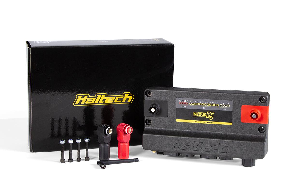
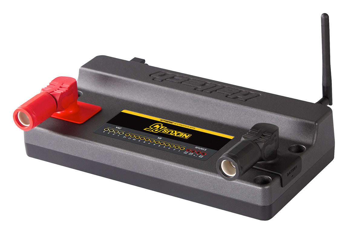
- NEXUS R5 VCU, SurLok connectors (Red and Black), Wi-Fi antenna, mounting bolts, USB-C Cable, USB-C dust cap, USB drive with NSP Software.
Applications
Racing application where advanced race features, data logging and power management control is required. Unsure about fitment for your build? Send us your engine and chassis details before ordering and we will confirm compatibility.
Tuned By Shawn is a Platinum Haltech Dealer backed by real wiring and calibration experience. Pair this with a remote tuning session over live Zoom and go from install to a finished calibration without visiting a shop.
If you have any questions, you are always welcome to contact us. We'll get back to you as soon as possible, within 24 hours on weekdays.
-
Shipping Information
Use this text to answer questions in as much detail as possible for your customers.
-
Customer Support
Use this text to answer questions in as much detail as possible for your customers.
-
FAQ’s
Use this text to answer questions in as much detail as possible for your customers.
-
Contact Us
Use this text to answer questions in as much detail as possible for your customers.