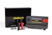
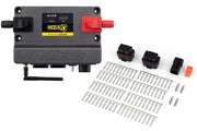
The Nexus R5 pinout diagram shows every pin on the Nexus R5 VCU connectors and what each one can do: its power and ground pins, engine outputs, sensor inputs, communications and general purpose outputs. It's the reference you need when you're:
- Wiring a universal harness, such as the R5 universal wire-in kit, into a car.
- Building your own loom from a R5 plug and pin set.
- Adding a sensor or output later and needing a pin that suits it.
- Tracing a fault with a multimeter.
What to check
- Make sure each pin's type matches the job. Input and output types are not interchangeable, so a sensor needs a suitable input and a load needs an output rated for it.
- Confirm you're reading the correct connector and looking from the correct side (wire side or pin side) before you push a terminal in.
- Cross-check your plan against the pin assignments in NSP, so the software and the harness agree.
Working with an R3 instead? See the Nexus R3 pinout.
Need this diagram? Ask us and we'll send it over with advice for your build.