The engine at a glance
Honda built the F20C for one car, the S2000. It is a 4-cylinder with a firing order of 1-3-4-2, and it came in a few versions depending on market and year.
| Version | Where | Displacement | Key differences |
|---|---|---|---|
| JDM F20C | Japan | 121.9 ci (1,997 cc) | 11.7:1 compression, 9,000 rpm redline |
| F20C (US, Euro, Australian) | USDM, EUDM and AUDM, all years for Euro and Aussie cars | 121.9 ci (1,997 cc) | Compression lowered to 11.0:1. Drive by wire from MY06 |
| F22C1 | US from MY04, Japan from MY06 | 131.6 ci (2,157 cc) | Longer stroke, 11.1:1 compression, 8,200 rpm redline. Drive by wire from MY06 |
The DBW change matters most when you plan the install. A cable-throttle car and a 2006-on car wire up quite differently, so confirm which you have before ordering parts. If you want a plug-in route, the Nexus S3 plug-n-play adapter harness kit for the S2000 connects to the factory loom.
Trigger setup
All the timing sensors on this engine are two-wire reluctor (magnetic) types. The crank wheel carries 12 evenly spaced teeth. Each camshaft has a 3-tooth wheel on its rear end, with the teeth 90 degrees apart, so the ECU effectively sees a 4-minus-1 pattern with one gap to find cylinder position.
Crank sensor
Find it near the timing cover. Wire it to the Trigger 4-core shielded cable:
- Trigger + (yellow) to sensor pin 2
- Trigger - (green) to sensor pin 1
- Pin 3 is not used
Cam sensors
There is one on the back of each cam at the rear of the head, and you only need one. Just remember the TDC offset depends on which one you choose. Both go to the Home 4-core shielded cable, with the ECU's yellow as Home + and green as Home -:
| Haltech wire | Sensor 1 pin | Sensor 2 pin |
|---|---|---|
| Yellow (Home +) | Pin 2, green lead | Pin 2, yellow lead |
| Green (Home -) | Pin 1, red lead | Pin 1, black lead |
If an engine won't sync, check polarity first. Our guide to checking crank and cam sensors walks through it.
TDC offset and timing drift
This is the part people get caught on. Haltech's unmodified test car lined up at a TDC offset of 709, but values of 33 (reported on a European car) and 20 have also been needed to align other vehicles. Treat any number as a starting point, lock the timing and verify with a timing light. See calibrating ignition timing.
Because the reluctor signal lags more as RPM rises, timing will drift unless you add an RPM-based trigger timing correction. After setting the offset at idle, check timing again at higher RPM and build the correction until the light agrees with the ECU across the range.
Ignition
Each plug has its own coil with a built-in igniter, driven straight from an ECU ignition output, so set the ignition system to direct fire. Use Constant Charge dwell mode with a Falling edge. Getting these wrong can kill the coils and possibly the ECU, so double-check before cranking.
- Coil pin 1: ECU ignition output
- Coil pin 2: ground to the cylinder head
- Coil pin 3: switched 12 V
Set dwell from coil data rather than guessing. Dwell time explains the trade-offs.
Throttle: cable or drive by wire
Cable throttle cars
The TPS is a simple 3-wire sensor. Pin 3 (yellow/blue) takes the ECU's 5 V supply, pin 1 (green/yellow) goes to signal ground, and pin 2 (red/black) carries the signal to a spare analog input.
2006-on DBW cars
From 2006 a separate module runs the factory electronic throttle, not the engine ECU. A DBW-capable Haltech such as the Elite 1500 or 2500 can read the pedal and drive the throttle body directly, removing that module from the loop.
| Throttle body pin | Job | Haltech wire |
|---|---|---|
| 2 (blue) | 5 V supply | 5V+ (orange) |
| 4 (green) | Sensor ground | Signal ground (black/white) |
| 1 (red/black) | Position sensor 1 | AVI-2 (orange/black) |
| 3 (red) | Position sensor 2 | AVI-3 (orange/red) |
| 5 (white/blue) | Motor | DBW1 (brown/black) |
| 6 (white/black) | Motor | DBW2 (brown/red) |
The pedal has two tracks, each with its own supply and ground. Supply pins 1 (yellow/blue) and 5 (yellow/red) both go to 5V+ orange; grounds on pins 2 (green) and 6 (green/white) go to signal ground. Pedal signal 1 is pin 4 (red/blue) to AVI-5 (orange/green), and pedal signal 2 is pin 3 (red/yellow) to AVI-4 (orange/yellow). Then run the DBW calibration.
VTEC and idle
VTEC here is a simple on/off lift change, so it runs through Cam Control Switched. The solenoid needs an output that can switch the high side. On an Elite, use a stepper output.
The idle air (bypass air control) valve has three wires but is set up as a 2-wire duty-controlled valve on one output. Pin 2 (yellow/black) takes switched 12 V, pin 3 (black/red) goes to a spare ECU output, and pin 1 (black) is ground.
Other sensors
| Sensor | Wiring | Our advice |
|---|---|---|
| MAP (on the throttle body) | Pin 3 (yellow/red) 5 V, pin 1 (green/white) ground, pin 2 (green/red) signal to a spare AVI | Fine for naturally aspirated use. Once you add boost, the ECU's internal MAP sensor is an option; for bigger boost, fit an external sensor on a spare AVI |
| Coolant and air temp | Two wires, either way round: one to a spare AVI, one to signal ground | Pick an AVI with a switchable pull-up, or add a 1k pull-up resistor to 5 V |
| Knock | Pin 1 knock signal, pin 2 signal ground | The factory resonant sensor tends to fail, sometimes with its green plastic body separating from the base. On a modified engine, swap to a non-resonant donut sensor like the Haltech-supplied Bosch knock sensor |
| Vehicle speed (Hall effect) | Pin 1 (yellow/blue) 5 V, pin 3 (brown/yellow) ground, pin 2 (blue/white) signal to a spare SPI | Calibrate it before using speed-based features |
| O2 | Factory narrowbands | Replace the pre-cat sensors with a wideband (below) |
Add a wideband
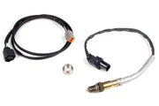
Narrowband sensors can't tell you actual mixture under load, so we'd fit a Haltech WB1 CAN wideband kit. Its LSU 4.9 sensor goes where the pre-cat sensors were, and they come out with a 22 mm wrench or socket.
Injectors
The factory injectors flow 380 cc/min, measured held fully open. Two things to know when entering data:
- If fuel pressure is fixed and not referenced to manifold pressure (common on returnless systems), map flow against manifold pressure or your fueling will be off as load changes.
- Dead time covers the time the injector takes to open and close, including the ramps where it isn't flowing fully. Enter proper dead time data across battery voltage. It makes a big difference to idle and light-load fueling.
Base maps and the factory ECU
Haltech has made base maps to suit its Elite adapter harnesses. They are imported into the ECU, not opened as a normal file, and Platinum Pro maps come with the older ECU Manager software. Base maps get you started; they are not a finished tune. If you need the factory ECU location or pinout diagram, ask us and we'll send it with advice for your build.
F20C FAQ
What TDC offset should I use on my S2000?
There isn't a single answer. 709 worked on Haltech's stock test car, but others have needed different values. Always confirm with a timing light, then check it again at higher RPM.
Can the ECU run the factory drive by wire throttle?
Yes. A DBW-capable Haltech can read the factory pedal and drive the throttle body directly, replacing the separate throttle module.
How is it different from a K series?
Compare it with our Honda K series and B series notes. The biggest differences are the trigger layout and VTEC control. Want a hand with your build? Book a free 30-minute consultation.