Why log EGT?
EGT tells you how hot the exhaust leaving the engine is. It rises with load, lean mixtures and late ignition timing, so it's a useful second opinion next to your wideband and knock data. On multi-sensor setups, comparing cylinders shows you which one is working harder, which helps with individual cylinder fuel trims or a failing injector. It's also a protection channel: a turbine, exhaust valves and pistons all have temperatures they don't like to see for long.
In NSP, EGT channels are set up through four nodes: Wiring, Sensor Configuration, Display and Diagnostics. We'll go in the order we actually set them up.
Wiring: position, input type and connection
| Setting | What it does | Our advice |
|---|---|---|
| Position | Records where the probe is in the engine | With one probe per cylinder, set each to the cylinder it measures. A single probe in the collector or downpipe stays Unassigned |
| Input Type | Chooses between Analog Input and Thermocouple - Type K | Most installs use a Haltech CAN thermocouple amplifier, so pick the thermocouple option |
| Connections | The physical input the probe uses | On a TCA, this is the port on the TCA the probe plugs into |
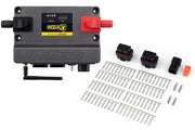
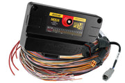
EGT probes are K-type thermocouples, which produce a tiny voltage that an ordinary ECU input can't read directly. That's the job of a thermocouple amplifier. Haltech's CAN units, the TCA2, TCA4 and TCA8, read the probes and send temperatures to the ECU over CAN. Pick the one with enough channels for the number of probes you plan to run. Getting the Position right matters on per-cylinder setups, because it's how you know which trace belongs to which cylinder when you read a log.
The Analog Input option is for an external EGT controller that outputs a voltage signal wired into an ECU analog input.
Sensor Configuration: calibration
What you see here depends on the input type.
- Thermocouple - Type K: nothing to do. The screen is empty and shows No Calibration Required, because the TCA already sends a temperature.
- Analog Input: enter the external controller's voltage vs temperature calibration here. Use the controller maker's published figures. A wrong calibration gives you a believable-looking number that's simply incorrect, which is worse than no number at all.
If you'd rather see Fahrenheit or Celsius, change it under Preferences > Unit Options. That only changes how NSP shows the value; the ECU's behavior doesn't change.
Display: gauge ranges and warnings
| Setting | What it does |
|---|---|
| Display Minimum | Where EGT number displays, gauges and bars start their scale |
| Display Maximum | Where that scale ends |
| Warning Minimum | Below this, EGT displays switch to their low warning state |
| Warning Maximum | Above this, they switch to their high warning state |
Set the display range a bit wider than you ever expect to see, so a gauge never pins at the end of its scale. The high warning is the useful one on the dyno; place it where you'd want to lift and take a look, not where parts are already failing.
Diagnostics: turning a hot reading into a fault
This node sets up a trouble code for the EGT channel.
- Maximum is the highest temperature you'll allow on this sensor. Go above it and the DTC is set.
- DTC Severity decides how seriously the ECU treats it, which ties into your engine protection strategy.
If the probe runs through a TCA, the minimum and maximum voltage DTCs are switched off, since the ECU isn't reading a raw voltage. The over-temperature check still works. Code meanings are listed in the DTC index.
Safe EGT depends on the engine, fuel, turbo and where the probe sits. A probe right at the port reads hotter than one in the collector. Take the turbo and engine maker's guidance, start conservative, and tighten limits only after you've logged a few hard runs.
Troubleshooting
| Symptom | Usually |
|---|---|
| EGT channel reads nothing | TCA not enabled or not on the CAN bus, or the wrong port selected under Connections |
| Traces are swapped between cylinders | Position set wrong, or probes plugged into the wrong TCA ports |
| Reading looks plausible but wrong | Analog Input chosen with a missing or incorrect calibration |
| No voltage fault codes available | Normal when using a TCA |
For a deeper look at probe choice and placement, read EGT sensors: everything you need to know.