BP-4W at a glance
| Spec | Value |
|---|---|
| Layout | Inline 4-cylinder |
| Displacement | 112 ci (1839 cc) |
| Firing order | 1-3-4-2 |
| Found in | 1999-2000 Mazda MX-5 Miata (NB1) |
| Factory ECU location | Under the passenger-side floor panel, up against the firewall |
| Factory injector flow | 265 cc/min |
If you'd rather not wire from scratch, the plug-in route is the Nexus S2/S3 NB adapter harness or the Elite 750 and 1500 NB plug-in kits. The rest of this guide is still worth reading, because it explains the settings those harnesses rely on.
Engine position: crank and cam triggers
Both triggers on the BP-4W are Hall Effect sensors, which keeps the setup simple since there's no reluctor signal to fuss with.
- Crank: a four-tooth plate sits behind the inner crank pulley. Two of those teeth are opposite each other and slightly offset from the other pair. The sensor lives at the front of the engine, on the right side of the crank, held by one bolt.
- Cam: the target is on the front of the intake cam gear. It has three teeth: two spaced 180 degrees apart, one of which has an extra tooth right next to it.
Both sensors share the same pin layout. The only difference is which Haltech loom you use: the crank goes to the Trigger 4-core cable, the cam to the Home 4-core.
| Sensor pin | Job | Haltech wire |
|---|---|---|
| A | Switched 12V supply | Red |
| B | Signal out | Yellow |
| C | Signal ground | Blue |
The crank sensor's single mounting bolt can work loose if something knocks it, and the air gap changes with it. The cam sensor's connector is known for poor contact. If you get sync errors or random trigger faults, check both of these before you touch any settings.
Ignition
Spark comes from two dual-post coils at the back of the head, fired in wasted spark. Each coil has its igniter built in, so it wires straight to a Haltech ignition output without an external igniter module.
- Pin A: switched 12V
- Pin B: unused
- Pin C: ground, to the cylinder head
- Pin D: trigger from the ECU ignition output
In the software, choose Waste Spark mode, Constant Charge, and a Falling Edge trigger. Dwell data for these coils exists as a chart. If you need it, ask us and we'll send it over with advice for your build.
Throttle position sensor
The NB1 uses a cable throttle with a three-wire position sensor.
| Sensor pin (factory color) | Job | Haltech connection |
|---|---|---|
| A (light green/white) | 5V reference | 5V+ (orange) |
| B (black/red) | Signal ground | Signal ground (black/white) |
| C (green/black) | TPS signal | A spare AVI, for example AVI-10 (white) |
Load sensing: MAP and MAF
There's no factory MAP sensor on this engine. The ECU's internal MAP sensor covers naturally aspirated and mild boost builds. Once you're past what it can read, plumb in an external sensor such as a 3 bar GM MAP sensor and wire it to a spare AVI.
Most people delete the MAF on a Haltech build, but you can keep it for logging if you want. Its pins: A (black/blue) to signal ground, B (pink) is the signal and goes to a spare AVI, and C (white/red) is its 12V feed.
Temperature sensors
Coolant
The coolant sensor has three pins. Two belong to the ECU, and the third drives the dash gauge and grounds through the block. Connect pin A (signal) to a spare AVI and pin B to signal ground, and leave pin C for the gauge.
Intake air
The factory air temp sensor sits in the stock airbox. It's a two-wire sensor and polarity doesn't matter: one pin to a spare AVI, the other to signal ground. If the airbox goes or you delete the MAF, fit a replacement air temp sensor in the intake pipe, ideally close to where the MAP sensor takes its reading.
Both temperature sensors need a pull-up to read correctly. Use an AVI that has a selectable pull-up, or add an external 1k resistor from the signal to 5V.
Idle air control
Idle speed is managed by a two-pin bypass air control valve. Pin 1 is the open signal and goes to a spare output, which the ECU duty cycles. Pin 2 takes switched 12V.
Knock sensor
The stock knock sensor is an older resonant type. It will work with an Elite 1000 or higher, but these sensors have a reputation for being unreliable and they aren't a good fit for a heavily modified engine. Wiring is simple: pin A is the knock signal, pin B is signal ground. If you get inconsistent readings, swap to a donut-style non-resonant sensor such as Haltech's genuine Bosch knock sensor. Our knock explainer covers why it's worth the effort.
Oxygen sensors
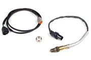
The factory narrowband sensors are fine for emissions-style closed loop, but you can't tune an engine properly with them. We strongly recommend a WB1 single-channel wideband kit, with its LSU 4.9 sensor going into the pre-cat sensor bung. A 22 mm wrench or socket gets the old one out.
VICS intake runner valve
Mazda's Variable Inertia Charging System opens a resonance chamber in the intake to change the effective runner length. The Haltech controls it with the Dual Intake Runner function and one spare output driving the solenoid. On the factory setup, the solenoid is energized below about 5200 rpm. Tune the switch point on the dyno if you've changed the cams or intake.
Vehicle speed
The speed sensor itself is a reluctor, but its signal goes to the speedometer first, which converts it to a clean digital square wave for the ECU. How you set up the SPI depends on where you tap in:
- From the speedometer output (usual): Hall Effect, Falling edge, pull-up Disabled.
- Straight from the sensor: Reluctor, Falling edge.
Pin 1 is the signal to any spare SPI, and pin 2 is signal ground. A good starting calibration is roughly 2780 pulses per km (about 4470 per mile). Fine-tune it against a GPS.
Alternator control
The ECU sets the charging voltage on this engine by sending the alternator a high-side duty signal. Use a spare stepper output and set both Active State and Drive Type to High. The grey/red wire (terminal D) takes that duty signal. The grey wire (terminal P) is a voltage feedback line and isn't connected to the Haltech.
Injectors
The factory injectors flow 265 cc/min, measured wide open at 100% duty. If your fuel system has a fixed regulator that isn't referenced to manifold pressure, map the injector flow against manifold pressure so fueling stays accurate as boost or vacuum changes.
You'll also need dead time data. That's the part of each injection pulse where the injector is still opening or closing and not flowing its full rate. It's plotted against battery voltage, and getting it right is what keeps idle and cruise fueling stable. See our injector dead time guide, and ask us if you need the factory dead time chart.
Base maps
Base maps exist for the Elite adapter harnesses. They must be imported into the ECU rather than just opened. Our base map basics article explains what a base map will and won't do for you.
Other Miata engines
Working on a different generation? See the NA6 B6-ZE, NA8 BP-ZE and NB2 BP-Z3 (BP-VE) guides.
NB1 Miata FAQ
Can I keep the stock crank and cam sensors?
Yes. They're Hall Effect sensors that Haltech reads directly. Just check the crank sensor bolt and the cam connector if you see trigger errors.
Do I need an external MAP sensor for a turbo NB1?
For low boost the internal sensor is fine. Once your target gets close to its limit, add an external MAP sensor so you have headroom above your peak boost.
Is the factory knock sensor usable?
It works with an Elite 1000 or higher, but we'd replace it on any serious build. A non-resonant sensor gives far more trustworthy data.