The B6-ZE at a glance
| Item | Value |
|---|---|
| Cylinders | Inline 4 |
| Displacement | 97.5 ci (1597 cc) |
| Firing order | 1-3-4-2 |
| Ignition | Two dual-post coils in wasted spark, external igniter |
If you'd rather not build a harness at all, the Elite 1500 + Miata NA plug 'n' play kit and the Elite 750 version plug into the factory loom, and Haltech ships base maps for the adapter harnesses with the ESP software. The rest of this page is for wire-in installs, or for anyone who wants to understand what the plug-in harness is doing.
Crank angle sensor (trigger and home)
Timing comes from the cam angle sensor. It holds two Hall effect channels: one with four pulses per cycle (labeled SGT) for trigger, and one with two pulses (SGC) for home. The sensor runs on 12V.
| Sensor pin | Job | Haltech wire |
|---|---|---|
| 1 (black) | Ground | Blue in the Trigger 4-core (signal ground) |
| 2 (white/red) | 12V feed | Red in the Trigger 4-core |
| 3 (white) | SGT, 4 pulses, trigger | Yellow in the Trigger 4-core (Trigger +) |
| 4 (yellow/blue) | SGC, 2 pulses, home | Yellow in the Home 4-core (Home +) |
The one-cable trick
Because both channels are Hall effect, the Trigger - (green) wire in the trigger cable has nothing to do. The Home cable, meanwhile, is only needed for one wire. Many installers move the green wire at the ECU plug so it lands on the Home + pin. Then a single shielded 4-core carries power, ground, trigger and home, and the Home cable can be left out of the engine bay.
- Elite 550, 750 or 950: pull the yellow wire out of pin A32 and insulate it (it goes unused). Then take the green wire out of A33 and push it into A32.
- Elite 1000, 1500, 2000 or 2500: pull the yellow wire out of pin B2 and insulate it. Then take the green wire out of B5 and push it into B2.
Write the change on the harness and in your notes. The next person to work on the car will expect the green wire to be Trigger -, and the Home cable to exist.
Coils and igniter
The factory setup runs two coil packs in wasted spark through an external igniter, and the igniter pinout is printed right on its body. Only the two input pins connect to the Haltech. Everything else stays on its factory circuit.
| Igniter pin | Job | Where it goes |
|---|---|---|
| IB1 | Input for coil 1 | Ignition output 1 (yellow/black) |
| IB2 | Input for coil 2 | Ignition output 2 (yellow/red) |
| OC1 / OC2 | Drives each coil negative | Factory wiring to the coil |
| VB | 12V | Factory ignition switch feed |
| TAC | Tachometer signal | Factory wiring to the tach |
| GND | Ground | Cylinder head |
| IGf | Ignition confirmation | Not used |
If the original igniter is missing or tired, an HPI4 high power igniter does the job using just two of its four channels. The HPI quick start guide covers its wiring. Need the factory dwell settings for these coils? Ask us and we'll send them over with advice for your build.
Throttle position sensor
Here's the first gotcha. Automatic cars have a 4-pin sensor that reads actual throttle angle. Manual cars have a 3-pin part that is just a closed-throttle switch, and the Haltech can't use it. If your car has the 3-pin switch, replace it with the 4-pin type.
| 4-pin TPS pin | Job | Haltech wire |
|---|---|---|
| 1 (VCC) | 5V supply | 5V+ (orange) |
| 2 (VTA) | Throttle signal | Spare AVI |
| 3 (IDL) | Idle switch | Leave unconnected |
| 4 (E2) | Ground | Signal ground (black/white) |
Idle, MAP and temperature sensors
- Idle valve: a 2-pin bypass air control (BAC) valve that the ECU pulses with one output. Pin 1 to a spare output, pin 2 to switched 12V.
- MAP: none from the factory. Use the Elite's internal sensor, or for real boost, an external one such as the 5 bar TI MAP sensor on a spare AVI.
- Coolant temperature: two wires, no polarity. One to a spare AVI, the other to signal ground.
- Air temperature: the factory sensor is part of the MAF. If the MAF goes, fit a separate sensor like the HT-010206, wired the same way as coolant temperature.
For both temperature sensors, pick an AVI with a switchable pull-up and turn it on. Otherwise add a 1k resistor between the signal and 5V.
The MAF and the fuel pump
The second gotcha. The Miata's factory MAF has a switch inside it that turns the fuel pump on as soon as any air moves through it. Unplug or remove the MAF and the pump stops running. When you delete it, the fuel pump has to be put under ECU control instead, normally with the Elite's fuel pump output driving the pump relay. If you're unsure how to rework your car's pump circuit, ask us for the diagram.
If you keep the MAF, here is how its seven pins map across:
| MAF pin | Job | Haltech wire |
|---|---|---|
| 1 (FC) and 2 (E1) | Fuel pump switch and its ground | Not connected to the ECU |
| 3 (E2) and 5 (E2) | Sensor ground | Signal ground (black/white) |
| 4 (VC) | 5V supply | 5V+ (orange) |
| 6 (VS) | Air flow signal | Spare AVI |
| 7 (THAa) | Air temperature signal | Spare AVI |
Oxygen sensor
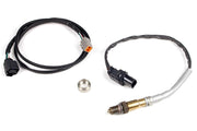
The B6 uses a single-wire narrowband sensor. The Elite can read it, but you can't tune with it. Swap it for a WB1 wideband kit, putting the supplied LSU 4.9 sensor in the factory location. You'll be working from under the car, with a 22 mm socket or wrench.
Injectors and the factory ECU
Injector flow and dead time for the stock injectors are already in the base map that installs with ESP. The factory ECU sits under the passenger footwell near the firewall: lift the carpet and remove the cover panel to reach it.
NA6 FAQ
Does this apply to the 1994-97 1.8L?
No, the 1.8 liter cars use the BP engine, which has its own page: see our 1994-97 NA8 BP-ZE guide. The later 1999-2000 NB1 BP-4W guide covers the next generation.
Can I keep the narrowband for closed loop cruise?
You can wire it in, but with a wideband fitted there's no reason to. A wideband gives you real numbers everywhere, not just at stoich.
Why does my car crank but not start after a MAF delete?
Most often the pump isn't running. Check that the ECU is driving the pump relay before chasing anything else.