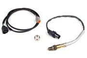
The TurboLamik TCU runs the ZF 8HP; your Haltech keeps running the engine. The TCU pretends to be a Haltech I/O expander box on CAN, which is how gear position and a torque reduction request get into the Haltech. Because a standalone ECU can't hand the TCU an accurate engine torque number, the TCU works torque out from manifold pressure, and that torque table has to be right or shifts will be rough.
Before you touch a laptop
Check off these four things first. If any of them is missing, nothing below will work properly.
- The mechatronics is converted. The 8HP's internal controller board has to be swapped for TurboLamik's board. It's delicate soldering work, and TurboLamik will do it for you if you send the unit in. Our 8HP and TurboLamik overview covers this step.
- The TCU can see four engine signals: throttle position, the brake pedal, engine RPM and engine load (torque). They can arrive as wired analog inputs or over CAN.
- The TCU has a MAP signal. On a Haltech build the TCU calculates torque from boost/vacuum, so either wire a MAP sensor straight to the TCU or pick MAP up from CAN (in TunerPro that's MAP input
13). - You have a way to choose gears: a supported CAN shifter, paddles or a DCT-style shifter, or an analog selector or switch.
Step 1: Set up the TCU (TunerPro RT)
Open your TCU file in TunerPro RT. Everything CAN-related lives under CAN › Can2 (Engine) in the parameter tree; the custom transmit settings are in Custom Can TX.
| Setting | Value | What it does |
|---|---|---|
| Sensor Call. › Sensor Input (DBW input) | 13 with drive-by-wire, 0 without | Drive-by-wire input source; leave it at 0 on a cable throttle |
| Can2A Type CAR | 8 | Engine-side CAN type TurboLamik specifies for Haltech |
| Can2 Speed | 4 | Engine CAN bus speed setting TurboLamik specifies for Haltech |
| Custom Can TX › Send ID | 704 (decimal) | Base ID for the messages the Haltech reads as an expander box |
| Send ID+0 and Send ID+1 | Both ticked (Set) | Turns on the two messages that carry the analog channels |
| Analog Can Out maximum value | 4095 on all eight channels | Full scale, so 0-5 V in the Haltech covers the whole range |
| Analog Can Out (channels 1-4) | TurboLamik's example uses 13, 14, 18, 25 | Picks which TCU value goes out on each virtual analog input |
In TurboLamik's example, analog channel 2 is the gear position and channel 3 is the torque reduction request. On the Haltech they show up as I/O Box A analog inputs 2 and 3, which is how the steps below use them.
Step 2: Turn on the expander boxes in the Haltech (NSP)
- Go to Haltech CAN System (see our Haltech CAN System article).
- Under Input/Output Expander Boxes, enable I/O Expander 12 (Box A) and I/O Expander 12 (Box B). Leave DTC Severity at None unless you want a warning when the TCU drops off the bus.
- Write the change and power cycle. Box A's analog inputs (IOA AVI 1-4) should now appear when you assign inputs, with live voltages showing.
If an actual IO12 box already uses Box A, the two will fight over the same CAN ID. Settings that flash or flicker in the TCU after you set up CAN are the classic symptom. Move one of them to a different address in both the TCU and the ECU.
Step 3: Gear position
Go to Transmission and set:
- Transmission Type: Auto with separate controller
- Drive Type: whatever your car is (the example is Rear Wheel Drive)
- Number of Forward Gears: 8
- Gear Detection Type: Gear Position Sensor
- Enable the Gear Ratio function
Then in Gear Detection Wiring, assign Gear Voltage Input to IOA AVI 2 and leave Pull Up on Disable. In Gear Detection Position, enter the voltage the TCU sends for each gear:
| Gear | Nominal voltage | Tolerance |
|---|---|---|
| Reverse (enable it) | 0.00 V | 0.10 V |
| Neutral | 0.50 V | 0.10 V |
| 1st | 1.00 V | 0.10 V |
| 2nd | 1.50 V | 0.10 V |
| 3rd | 2.00 V | 0.10 V |
| 4th | 2.50 V | 0.10 V |
| 5th | 3.00 V | 0.10 V |
| 6th | 3.50 V | 0.10 V |
| 7th and 8th | Keep going in 0.5 V steps | 0.10 V |
TurboLamik's screenshot stops at 6th, so confirm 7th and 8th against the live IOA AVI 2 voltage, or use the Calibrate button in each gear. More on these settings in Gear Detection and Gear Ratios.
Step 4: Torque reduction during upshifts
When the TCU wants torque pulled for an upshift, it raises the voltage on IOA AVI 3. TurboLamik uses an ignition Generic Correction to turn that voltage into timing retard:
- Go to Ignition Tuning › Corrections and enable Generic 1 Correction.
- Set the table's first axis to IOA AVI3 V with breakpoints 0, 2.5 and 5.0 volts.
- Set the second axis to Base Ignition Angle (TurboLamik uses -10° to 50° in 10° steps).
- Fill the table so 0 V removes nothing, 2.5 V pulls a share of the timing, and 5 V pulls a lot.
In TurboLamik's example the 0 V column is all zeros, the 5 V column is -60° everywhere, and at 2.5 V the retard grows with the base timing (for example -8° at 10° base and -40° at 50° base). Treat that as a shape to start from, not a finished map, and check in your logs that the cut lands where the TCU asks for it.
Step 5: Teach the TCU your engine's torque
This is the step people skip, and it's the usual cause of harsh or slipping shifts. A standalone ECU doesn't send a trustworthy torque value, so the TCU estimates it from MAP using a base torque table you have to scale to your engine.
- In TunerPro, open Torque Calculation, enable Automatic detection of torque calculation input and set Torque Calculation Input to
0. - Pick the Base Torque Table RPM/MAP that uses the torque units you like.
- Scale the whole table to your engine. Divide your engine's peak torque by the table's peak value, select every cell and multiply by that number. That table only covers up to atmospheric pressure; a separate pressure-to-torque multiplier handles boost, and it usually doesn't need changing.
- Save and upload to the TCU.
- Start the engine. At idle with no load, the TCU's engine torque reading should sit around 10-20 Nm (7-15 lb-ft). Turn on data tracing in TunerPro so you can see which cells you're in, and nudge them until it does.
- Repeat the check holding steady at about 3,000 rpm and 5,000 rpm with no load.
- Look at the table in 3D and smooth out any spikes. Big cams and rotaries may need larger changes.
- Drive gently first and make sure shifts are smooth and the clutches aren't slipping for a long time.
Step 6: Brake and paddles
The TCU needs the brake pedal signal, either from CAN or wired to the TCU. Paddles are wired as ground-switched inputs on the TCU's analog inputs 11 and 12, which are enabled by default. With paddles as your only shifter:
| To get | Do this |
|---|---|
| Drive (first gear) | Hold the brake and pull upshift |
| Reverse | Hold the brake and pull downshift twice |
| Park | Hold the brake and hold downshift for 2 seconds |
If you also have a CAN shifter (BMW, Dodge, a CAN keypad), the shifter is in charge of P/R/N/D and the paddles only request up and down shifts while you're in a forward gear.
Our tip: split each paddle wire and run it to a spare Haltech input as well, set up with Paddle Shift Inputs. The ECU then sees the shift request at the same instant as the TCU, which keeps flat shift cut and blip timing tight.
Troubleshooting
| Symptom | Usually |
|---|---|
| Values flash or flicker in the TCU after CAN setup | Two devices on the same CAN ID. Change the address in the TCU and the ECU. |
| No IOA AVI channels in the Haltech | Box A not enabled in Haltech CAN System, Send ID not 704, Send ID+0/+1 not ticked, or bus speed mismatch |
| Haltech shows the wrong gear | Gear voltages or tolerance off; recalibrate each gear against the live voltage |
| Harsh, slow or slipping shifts | Torque table not scaled to the engine (Step 5) |
| Won't go into gear on paddles | No brake signal reaching the TCU |
FAQ
Do I need a real Haltech I/O box?
No. The TurboLamik imitates one over CAN. You only enable the box in the Haltech software.
Can I get more than gear and torque reduction into the Haltech?
Yes. The expander-box method gives you up to eight analog channels; Haltech's generic CAN lets you bring in everything the TCU broadcasts. See our CAN bus overview.
Can you set this up for me?
Yes. Book a free consultation and we'll help plan the wiring and setup for your 8HP swap. Running a CANTCU instead? See our CANTCU and Haltech setup guide.