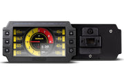
What the uC-10 is, and who it suits
The uC-10 is a 10-inch, low-profile TFT dash with an optically bonded screen, so it stays readable when the sun is coming straight through the windshield. It talks CAN, which means it can pull data from a Haltech ECU, from a car's CAN-based OBD-II port, or from a handful of other brands of aftermarket ECU through adaptor looms. Setup is done in the same NSP software used for Nexus ECUs.
We like it for two kinds of build: full cluster replacements, where the dash has to cover indicators, warning lights, the tacho signal and alternator excitation, and race cars that want a big, clear screen with a few extra inputs and outputs on board.
What comes with it
- The uC-10 dash itself
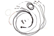
- A main harness for the 34-pin connector, plus spare pins
- A DTM-4 to DTM-4 CAN cable, 3000 mm (120 in) long
- A USB-A to USB-C cable and a dust cap for the USB-C port
- Three M5 x 8 mm mounting screws
- Two pre-wired momentary push buttons (22 AWG leads, 800 mm)
- A glass-mount Wi-Fi antenna
- A quick start guide
Getting power and data: pick your CAN connection
The uC-10 has no life of its own until it's on a CAN bus that also feeds it power. Which route you take depends on what's running the engine.
| Your setup | How to connect | Things to watch |
|---|---|---|
| Haltech Nexus or Elite | Plug the supplied main harness into the back of the dash, then run the DTM-4 cable from the harness to the ECU, a spare port on a WB1/WB2, or a spare port on a CAN hub | On ECUs with more than one CAN channel, the dash must sit on a channel set to the Haltech CAN protocol. On the wrong channel it lights up but shows no ECU data |
| Haltech Platinum | Same as above, plus a DTM-4 to 8-pin Tyco adaptor, the HT-130040 CAN adaptor cable | One ships with the ECU. Buy a replacement if yours has gone missing |
| Factory CAN OBD-II | The HT-135003 OBD-II to CAN cable (sold separately) | Its red wire must go to a key-on 12V feed. The OBD-II port is live all the time, so skipping this leaves the dash powered with the key off |
| Supported third-party ECU | One of the adaptor looms below | Confirm your ECU model and CAN connector before ordering |
On a Haltech system the CAN cable carries switched power and ground as well as data, so the dash wakes up the moment the ECU does, usually when you turn the key to on.
Third-party ECU adaptors
At the time of writing the uC-10 supports Link (Atom, Monsoon, Storm, Extreme, Fury, Thunder, Force GDI and G5), MoTeC M1 and the older M400/M600/M800 units, Microtech, MaxxECU and Syvecs. The loom you need depends on the connector your ECU uses for CAN:
- HT-130046: flying leads with pins for an AMP Superseal connector. Suits Link Atom and Monsoon, and MoTeC units that bring CAN out on a Superseal.
- HT-130047: a 6-pin circular M12 plug for the front CAN port on Link Storm, Extreme, Fury, Thunder and Force GDI.
- HT-130048: a 5-pin JST plug with a flying power lead, for Link G5 plug-in ECUs.
- HT-130049: a 4-pin Molex Mini-Fit Jr plug for Microtech.
Connecting to NSP, by USB or Wi-Fi
Install NSP from our downloads page or Haltech's, then power the dash and plug the USB-C cable into the port on its face. NSP finds the dash on its own and goes online. From there you can build screens, set up warnings and alarms, and assign any sensors or devices you've wired straight to the dash. Changes show up on the screen as you make them, which makes layout work quick.
Wi-Fi is an alternative to the cable once it's switched on, and it needs firmware 2.27.0 or newer. Early units shipped with the hardware and antenna but without the feature enabled, so update first if you're on older firmware. To turn it on:
- Go online over USB.
- Under Connections, enable the Wi-Fi module.
- Open the Wi-Fi page and choose an SSID (at least one character) and a password (eight characters or more), then click Apply.
- With the dash powered from the ignition, join that network from your laptop's network settings.
More on the Wi-Fi settings is in our Wi-Fi article.
The 34-pin main connector: what you can wire in
Pin 3 is switched +12V and pin 4 is ground. On most installs you never touch them because the CAN cable feeds both. With the OBD-II cable, the switched feed comes through that cable's red wire instead.
| Resource | Qty | What it handles | Our advice |
|---|---|---|---|
| Analog voltage inputs (AVI) | 10 | 0-5V sensors (pressure, temperature, position) and on/off switch signals | Turn on the software 1K ohm pull-up for temperature sensors and ground-switched inputs. Leave it off for sensors with their own 5V supply. AVI 1 also offers a 240 ohm pull-up, which suits many fuel level senders |
| Synchronized pulsed inputs (SPI) | 4 | Frequency and duty signals, plus anything an AVI can read. Hall, optical or reluctor sensors, up to 25V and 15 kHz | Use these for wheel speed, flex fuel or the GPS speed input module, which wires up the same way it would to an ECU |
| Digital pulsed outputs (DPO) | 4 | Relays and small solenoids, up to 3A, as on/off, duty or frequency | These switch to ground, so feed the device 12V and let the DPO complete the circuit. Use a relay for anything heavier |
| Alternator excite | 1 | Replaces the charge warning lamp circuit | Use it when the factory cluster comes out, or the alternator may never start charging |
| Tacho input | 1 | A hard-wired RPM signal when RPM isn't coming over CAN | Accepts a clean square wave or a coil-negative signal, the kind you get from points or an external ignition module |
Why the alternator pin matters: many alternators need a small current through the charge light to wake up. Pull the stock cluster and that path disappears. The uC-10's excite pin stands in for the bulb, so you don't need to add a resistor.
Push buttons
The two supplied buttons ground their black wires on pins 13 and 14. The signal wires go to AVI 10 and SPI 4. The usual setup has one button paging through screens and the other clears alarms. You can also set them up as next and previous screen buttons if you'd rather scroll both ways.
Indicators and warning lights
For a street car, turn signals and the usual warning lamps have to keep working. Several AVIs come pre-assigned to those jobs in NSP. Tap them into the car's existing lamp wiring, then set the on and off voltage thresholds so each light switches cleanly. If a light flickers or never comes on, the threshold is the first thing we check.
Reverse camera
Every uC-10 has a composite video input, enabled with firmware 2.29.0 or newer. Haltech's reverse camera kit includes the camera, a plate bracket and a 6 m harness that plugs into the main connector. Its red, yellow and black wires land on pins 7, 8 and 9.
There are two ways to bring the picture up:
- In Reverse: the dash switches to the camera when the Gear channel reads reverse (from CAN or your transmission setup, depending on gear detection type) or when a reverse switch is active.
- Input Switch: pin the kit's white wire to whichever input you assign as the camera trigger and feed it a signal such as the reverse lamp's 12V. AVIs 1 to 4 (pins 18 to 21) are the usual choice, but any free AVI or SPI works.
Crimp, don't solder. Crimp the pin, push the bottom tab to unlock the connector, slide the pin into the harness side, then push the top tabs to lock it. The HT-070300 crimper set is the right tool for these terminals.
Mounting options
- Moulded panel mount (HT-060091): 500 x 250 mm (about 20 x 10 in) and made to be trimmed to fit a cluster surround. Bolts to the dash with the supplied screws.
- Standard dash mount (HT-060070): holds the dash at 90 degrees to a flat surface.
- Tube mount (HT-060072): pairs with the standard mount to clamp onto a 1.25 in (31.75 mm) cage tube or steering column.
The full pinout table, wiring diagram, specification sheet and outline dimensions are diagrams we can't reproduce here. You'll find Haltech's guides on our dash and CAN device guides page.
Need this diagram? Ask us and we'll send it over with advice for your build.
Troubleshooting
| Symptom | Usually |
|---|---|
| Dash stays dark | No CAN power: loose DTM-4, ECU not powered, or the OBD-II cable's red wire not on a key-on feed |
| Dash powers up but all values are zero | Connected to a CAN channel that isn't running the Haltech protocol, or wrong adaptor/protocol for a third-party ECU |
| Dash stays on with the key off | OBD-II cable's red wire tied to constant 12V |
| Alternator not charging after a cluster swap | Factory cluster removed and the alternator excite pin not wired |
| Can't see the Wi-Fi network | Firmware older than 2.27.0, module not enabled, or dash only powered over USB |
uC-10 FAQ
Does the uC-10 need a Haltech ECU?
No. It will run from a CAN OBD-II port or a supported third-party ECU, and with multi-master CAN it can even control a PD16 or CAN keypad on its own.
Can it replace my factory gauge cluster?
Yes, and that's where the alternator excite pin, tacho input and pre-assigned indicator inputs earn their keep. Plan those circuits before you pull the old cluster.
Why do I get no ECU data on my Nexus?
Check which CAN channel the dash is on and that the channel is set to the Haltech protocol in the CAN settings, then make sure the dash is ticked in the Haltech CAN system page. If you'd like a hand planning a cluster swap, book a free 30-minute consultation.