Where this fits
A generic output has three parts: the conditions that decide when it turns on (see condition settings), the table that sets how much output you get (see generic output table), and the wiring page that connects it all to real pins. This article covers that last part. For the big picture, start with the generic output overview.
Options
Number of Outputs
One generic output can drive up to four pins at once. When its conditions switch it on, every pin you enable here turns on together. That's handy when one event needs several things to happen, such as two fans and a warning light, without building three separate generic outputs.
Stepper settings
If the Signal Type is 4-Wire or 6-Wire Stepper Position (%), three more options appear:
| Setting | Too low | Too high |
|---|---|---|
| Stepper Max Speed | The motor crawls to its new position | The motor skips steps and the ECU loses track of where it really is |
| Stepper Range | The stepper never reaches fully open | Calibration takes longer than it needs to |
Stepper Invert flips the direction the motor moves. If a position of 0% gives you a fully open valve, this is the fix, rather than rewiring.
We start with a moderate speed and increase it only while the stepper keeps tracking its commanded position reliably. A stepper that has skipped steps will quietly sit in the wrong place until the next calibration, so err on the slow side.
Connections
Override Switch
If you've enabled an override switch, choose the input it's wired to. An AVI or SPI works, or you can use a button on a Haltech CAN keypad, which saves running another wire. Override switches are great for a manual fan button or a "turn it on now" test during setup.
Output
Choose a free output pin for each output you've enabled. Remember the output drives a signal, not a heavy load: pumps, fans and anything drawing real current should go through a relay. Our relay guide explains why.
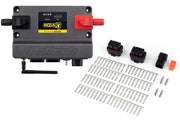
If you plan to use a pin on a CAN expander, check it's a suitable job for CAN IO first. Anything timing-critical belongs on the ECU itself. See functions not suited to CAN IO.