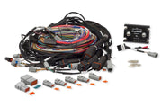
What the REM adds to an Elite 2500
The Race Expansion Module is a companion unit for the Elite 2500. It adds injector drivers and extra I/O, which is what lets the pair run up to 16 injectors in sequential staged mode and drive as many as 32 injectors in total. The ignition side still covers direct fire, wasted spark and distributor setups. On top of that, the REM's spare inputs are handy for data logging and it contributes to advanced functions such as traction control.
| REM hardware | Count | Notes |
|---|---|---|
| Injector outputs | 8 | Peak and hold, 0-8 A peak / 0-2 A hold |
| Digital pulsed outputs, low side | 4 | 1 A max |
| Digital pulsed outputs, high or low side | 4 | 1 A max |
| Digital pulsed inputs | 4 | Speed, switch and frequency signals |
| Analog voltage inputs | 10 | Sensors for control or logging |
If you're planning a build around one, the Elite 2500 + REM 16-injector wire-in harness is the easiest starting point, and the REM overview covers the unit itself.
The dedicated links between the two units
The two boxes don't just share data over CAN. Several hard-wired signals keep them in lockstep, and these are fixed in firmware, so you can't move them to other pins. Get them right first.
| Link | Elite 2500 pin | REM pin / destination | Why it exists |
|---|---|---|---|
| CAN | B23 and B24 (REM ECU connector) | REM CAN | All data between the units, including your USB session |
| Watchdog | SPI4 (B7) | IGN1 (A3) | Fast check that both units are online and error-free |
| Solid state relay | DPO4 (B19) to conditioning circuit pin 3 | DPO5 (A24) to conditioning circuit pin 2 | Both units control the relay that powers every injector stage |
| Stage 2 sync | DPO2 (A1) | B1 | Tells the REM when to fire stage 2 |
| Stage 3 sync | DPO3 (A3) | B2 | Tells the REM when to fire stage 3 |
| Stage 4 sync | DPO1 (A18) | B8 | Tells the REM when to fire stage 4 |
The shared solid state relay is the part people most often question. Because every stage draws from the same switched supply, the injector current control sees the same voltage on all of them, which keeps flow consistent between stages. The 26-pin and 34-pin REM connector pages list the rest of the pinout.
Label the sync wires at both ends while the loom is on the bench. A swapped stage sync wire won't stop the engine starting, it will just fire the wrong injector bank at the wrong time, which is a miserable thing to chase on the dyno.
Turning it on in ESP
- Connect the REM to the Elite 2500 over CAN and go online with the Elite 2500. You never plug USB into the REM: the Elite handles all communication.
- Go to Main Setup > Devices > Race Expansion Module and enable it.
- In the same menu you can also enable the REM's Auxiliary Inputs and Outputs. You can use those or Haltech I/O Expander 12 boxes, but not both at once, so decide early.
Setting up a second injector stage
A common layout is a V8 with one injector per cylinder on the Elite and a second set of eight on the REM. To configure that:
- Open Main Setup > Engine > Fuel and set Number of Stages to 2.
- In the staging setup for the second stage, choose 8 outputs, sequential, configured per cylinder.
- Use the driver drop-down to select REM, so the module drives those injectors.
Two duty cycle limits decide when stages come in and drop out:
- Maximum Stage Duty Cycle (default 80%): once the running stage hits this, the next stage switches on.
- Minimum Stage Duty Cycle: when duty falls to this under staging conditions, the highest active stage switches off. The ECU won't drop a stage if doing so would push the stage below it back over the maximum, so it holds on until that's no longer a risk. That stops the system from flicking a stage on and off.
Injector data comes before the first crank
Under Injection System in the ECU Navigator tree, every stage has its own firing angle, dead time, flow and current settings. Fill all of them in for every stage before you try to start the engine. Wrong dead times on the secondary bank are one of the fastest ways to end up with a lean spot the moment staging kicks in.
Check your work with the I/O Report
At the bottom of the Setup menu, View I/O Report shows every input and output and whether it's taken. With staging enabled you'll see the stage 2 sync output (DPO2, A1) listed as used and going to REM B1. The REM's own I/O appears on the left under Race Expansion Module, and anything free there can be assigned to features through the Functions button on the Setup (F4) page.
Troubleshooting
| Symptom | Usually |
|---|---|
| ESP can't see the REM | REM not enabled under Devices, or CAN wiring on B23/B24 open or swapped |
| Secondary injectors never fire | Stage driver not set to REM, stage sync wire missing, or SSR not getting both control signals |
| Lean or rich only when staging starts | Secondary injector data (dead time or flow) wrong |
| Auxiliary I/O options missing | I/O Expander 12 boxes already enabled; you can't run both |
FAQ
Can I reassign the REM sync or watchdog pins?
No. The watchdog, SSR and stage sync connections are fixed in firmware.
Does the REM work with other Elite models?
The REM is designed to pair with the Elite 2500. If you're weighing up a staged build, talk to us and we'll help you spec it.