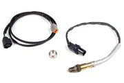
What you're connecting
This guide is written around the PPG 6-speed sequential used in R32, R33 and R34 Skyline GT-Rs. It assumes the gearbox came with PPG's Universal Display Harness and that you're using the PPG gear display. If you'd rather show gear on a Haltech dash and leave the PPG display out, skip ahead to the last section, because the sensor then needs its power from somewhere else.
Two signals come from the gearbox system into the ECU:
- Gear position: an analog voltage from a programmable position sensor, which the ECU converts into a gear number.
- Load cell: an analog signal from the shifter that changes when the driver pushes or pulls on the lever. The ECU uses it to know a shift is starting, which is the basis for flat shifting and throttle blips.
Wiring
| Wire color | Load cell | PPG harness, Chassis Interface connector C4 |
|---|---|---|
| Red | Switched 12V | Switched 12V |
| Black | ECU signal ground | ECU signal ground |
| White | Load cell signal, to a spare AVI | n/a |
| Pink | n/a | Gear position signal, to a spare AVI |
Use the ECU's signal ground for both, not a chassis ground. Both signals are analog, and a ground offset shows up as a wrong gear or a false shift request. Our ECU grounding guide explains why.
Programming the gear position sensor
The sensor inside the gearbox is programmable, and it has to be set up to give a clean, consistent output before the ECU can read it reliably. You'll need PPG's BladeCom software and the USB programming dongle supplied with the gearbox. PPG provides BladeCom and their installation guide to owners.
- Install BladeCom on your laptop.
- Plug the dongle into the laptop and connect its Deutsch DTM plug to the connector labeled Comms on the PPG harness.
- In BladeCom, go to Sensor Options and choose Detect Sensor. You should see the sensor version and serial number appear in the status bar at the bottom. If they don't, stop and check the connection before going further.
- Unlock the sensor for editing with Sensor Options then Allow Changes.
- Under Output Options, tick Reverse.
- Open the Manual Setup tab and enter the values for this application, pressing Set after each one so it's written to the sensor.
- Go back to Sensor Options and untick Allow Changes to lock the settings in.
- Unplug the dongle. The sensor is done.
- Program the PPG gear display next, following PPG's installation guide.
The Manual Setup values and the matching gear position voltages for the Haltech are shown in screenshots we can't reproduce here. Ask us and we'll send them over with advice for your build.
Setting up the Haltech
With the sensor programmed, set up the gear position input on the AVI you used and enter the voltage for each gear. The ECU compares the live voltage against those values to decide which gear you're in. Our gear position article covers the input setup, and load cell covers the shift sensor.
A tip from the workshop: after entering the values, sit in the car with the engine off and click through every gear while watching the gear number and raw voltage in the software. Each gear should show a stable voltage well away from its neighbors. If two gears read close together, recheck the sensor programming before you drive it.
Once gear and load cell are reliable, you can build on them with flat shift and throttle blip strategies. If the car runs a Haltech plug-in such as the Elite 2500 Skyline GT-R kit, check which spare AVIs are free before you start.
Running without the PPG gear display
The PPG display does more than show a number. It also contains a regulator that feeds the gear position sensor a steady 5V. Remove the display and the sensor loses its supply, so you have to provide 5V yourself.
The simplest way is through pin 4 of the Comms connector: connect it to the ECU's 5V sensor supply. Once that's done, the 12V feed into the harness Chassis Interface isn't needed any more. Using the ECU's own 5V and signal ground also means the sensor and the ECU share the same reference, which helps accuracy.
Troubleshooting
| Symptom | Usually |
|---|---|
| BladeCom doesn't show a serial number | Dongle not connected to the Comms plug, or the harness isn't powered |
| Gear voltages run in the opposite order to the values you expected | Check that Reverse is ticked in BladeCom Output Options |
| Gear position reads 0V or 5V constantly | No 5V to the sensor, often because the PPG display was removed without adding an external supply |
| Wrong gear shown or gear flickers | Gear voltages in the ECU don't match the programmed sensor, or a ground problem |
| Load cell triggers without touching the lever | Load cell threshold set too low or signal ground issue |
FAQ
Can a Haltech dash show the gear instead of the PPG display?
Yes. The ECU calculates gear number from the sensor and sends it to the dash. Just remember the 5V supply change above.
Does this apply to other sequential gearboxes?
The principles do: a gear position voltage and a load cell into AVIs. The sensor programming steps are specific to PPG. For help with another brand, book a free consultation.