What the diagram is for
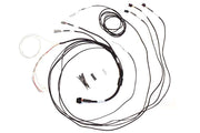
A semi-terminated harness comes with the ECU end fully built, and the other end left as labeled flying leads for you to connect to your engine and chassis. The harness diagram for the Elite VMS and VMS T maps each of those wires, showing which ECU function it carries so you can connect it to the right sensor, injector, coil or switch.
When you need it
- While terminating the harness during a wire-in install.
- When fault-finding a sensor or output that isn't responding.
- When adding a function later and looking for a spare input or output.
What to check
- Confirm each wire against the Elite VMS / VMS T pinout before you crimp it.
- Ground sensors to the ECU's sensor ground wires, not to the chassis, to keep signals clean.
- Check power, ground and communication with a meter before connecting the ECU.
- Cross-check against the universal wiring diagram and the ECU overview.
Need this diagram? Ask us and we'll send it over with advice for your build.